3 outline of data trace operations, Standard operations – Yaskawa MP900 Series Machine Controller for Standard Operation User Manual
Page 277
System Configuration Definitions
4.5.3 Outline of Data Trace Operations
4-20
4
4.5.3 Outline of Data Trace Operations
The three tab pages are switched between to set the trace trigger, check trace data, and per-
form other operations for tracing.
Standard Operations
A standard procedure for data tracing is given below.
1. Set the data trace trigger conditions on the Data Trace Definition Tab Page.
2. Start the trace.
3. Check the trace data list on the List Tab Page.
4. Set the graph scale and other parameters on the Graph Tab Page to display the trace data
in graph form.
5. Repeat the above steps to produce various trace data. It is often convenient to switch
between the list display and the graph display.
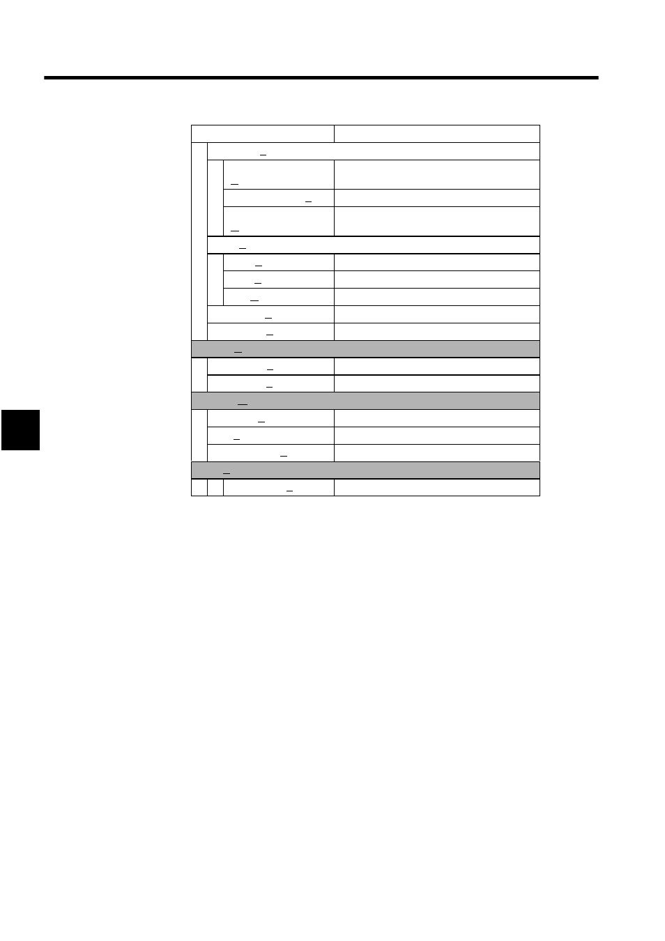
Sampling (S)
Number of read data
(R)
Changes the number of data to be read.
Trace Time Axis (T)
Changes the trace time axis.
Jump to Appoint Data
(O)
Displays trace data from any sample number.
Data (D)
DEC (D)
Displays trace data in decimal.
HEX (H)
Displays trace data in hexadecimal.
m/s (M)
Switches the time axis unit.
Next Page (N)
Displays the next tab page.
Back Page (B)
Displays the previous tab page.
Control (C)
Trace Start (S)
Starts the data trace.
Trace Stop (P)
Stops the data trace.
Window (W)
Cascade (C)
Stacks windows in the display.
Tile (T)
Lines up windows in the display.
Arrange Icons (A)
Lines up icons.
Help (H)
About App.. (A)
Displays version information.
Menu Command
Function