Yaskawa MP900 Series Machine Controller for Standard Operation User Manual
Page 424
7.4 Creating Table Programs
7-57
7
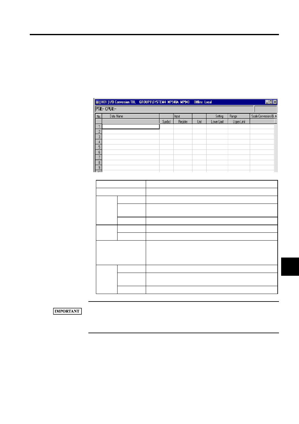
ues in the input registers according to the conversion equation and saves the results in the
output registers. An additional equation that checks the upper and lower limits can be added
for the results of the scale conversion. Subroutines can be called by using the XCALL
instruction in the main program.
Up to 200 rows of table data can be entered.
1 The input register and output register must be set. An error will occur when the table is saved if they
are not set.
2 I/O conversion tables cannot be created for user functions.
Setting Item
Details
Data Name
Enter a name of up to 36 characters.
Input
Symbol
Enter a symbol of up to 8 characters to be used for the input register.
Register
Enter the input register number. The current value will be displayed in
Online Mode.
Unit
Enter a unit of up to 8 characters for the input register value.
Setting
Range
Lower Limit
Enter the lower limit for the check after scale conversion.
Upper Limit
Enter the upper limit for the check after scale conversion.
Scale Conversion/Bit
Enter the equation for converting the input register values. Leave a
space between the input equation values and the operands. Refer to the
MP900 Series Machine Controller User's Manual: Ladder Program-
ming (SIEZ-C887.2C) for information on conversion equations.
Output
Symbol
Enter a symbol of up to 8 characters to be used for the output register.
Register
Enter the number of the output register to which the scale-converted
value is to be saved. The current value will be displayed when online.
Unit
Enter a unit of up to 8 characters for the output register value.