17 sva motion parameters settings – Yaskawa MP900 Series Machine Controller for Standard Operation User Manual
Page 181
Module Configuration Definitions
3.5.17 SVA Motion Parameters Settings
3-86
3
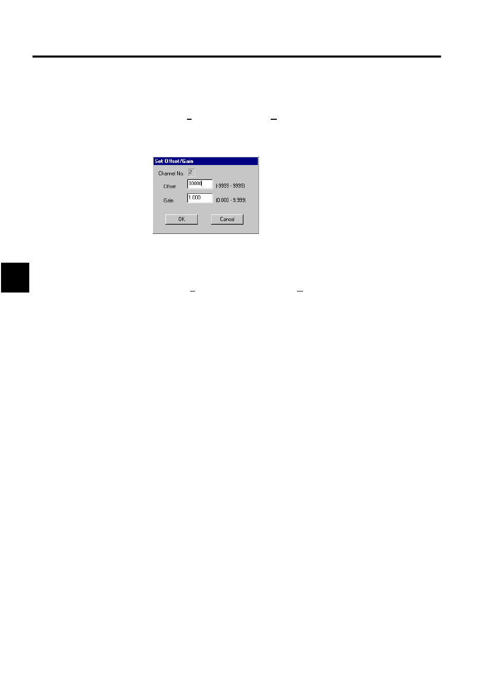
Setting the Offset and Gain
1. Click Set (S) and then Offset/Gain (O) on the Analog Output Definitions menu.
2. Input the desired offset and gain in the following dialog box and then click the OK But-
ton.
Deleting Allocation Data
1. Move the cursor to the channel number to be deleted.
2. Click Edit (E) and then Assignment Delete (D) on the Analog Output Definitions menu.
The data selected in step 1. will be deleted.
Saving, Deleting, and Closing Analog Output Definitions
Refer to the procedures in 3.3 Basic Individual Module Definition Operations for details.
3.5.17 SVA Motion Parameters Settings
This section explains how to set the motion parameters of the SVA Modules.
Outline of SVA Motion Parameter Settings
SVA Modules are available that control 2 axes per Module or up to 4 axes per Module.
The SVA Modules have either 2 or 4 connectors (CN1 to CN4) for connections to the SER-
VOPACKs. Each of these connectors has an analog output for speed reference, an analog
input for speed monitoring (SVA-02 only), a phase-A/B/C pulse input (5-V differential or
12-V), a pulse latch digital input, general-purpose digital inputs, and general-purpose digital
outputs.