Programming window configuration – Yaskawa MP900 Series Machine Controller for Standard Operation User Manual
Page 386
7.3 Creating Ladder Logic Programs
7-19
7
1 In the dialog box, set the Type Box to DWG to open the main drawing program, and set to FUNC to
open the main function program.
2 Up to 5 drawing number or function symbol programs can be open at the same time in the Program-
ming Window.
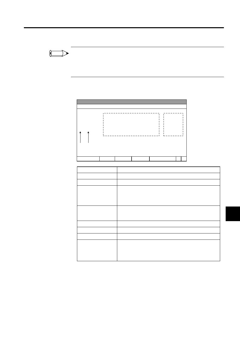
Programming Window Configuration
Display Item
Details
Level
Displays the nesting level of each program.
Step No.
Displays the step number of the instruction.
Program
For drawings, the program executed is displayed. For user functions,
the function's internal program is displayed.
The current value of each operand is also displayed while the pro-
gram is being executed.
Comments
Comments for the program being executed will be displayed. Refer
to 7.3.10 Creating Comments for information on how to create com-
ments.
D registers
Display the number of D registers set in the DWG properties.
# registers
Display the number of # registers set in the DWG properties.
Total No. of Steps
Displays the total number of steps for the program.
Operand Input Mode
Displays the operand input mode.
ADR: Register Input Mode
SYM: Symbol Input Mode
S-A:
Symbol/Register Input Mode
INFO
1 0000
1 0001
2 000n
・・・
・・・
・・・
・・・
・・・
・・・
PT# login information
Ladder program
Comments
Level Step No.
Starter line
D registers # registers
Total steps
Input mode
Drawing name Ladder.....