I/o data set tab page – Yaskawa MP900 Series Machine Controller for Standard Operation User Manual
Page 245
Module Configuration Definitions
3.7.9 CNTR I/O Definitions
3-150
3
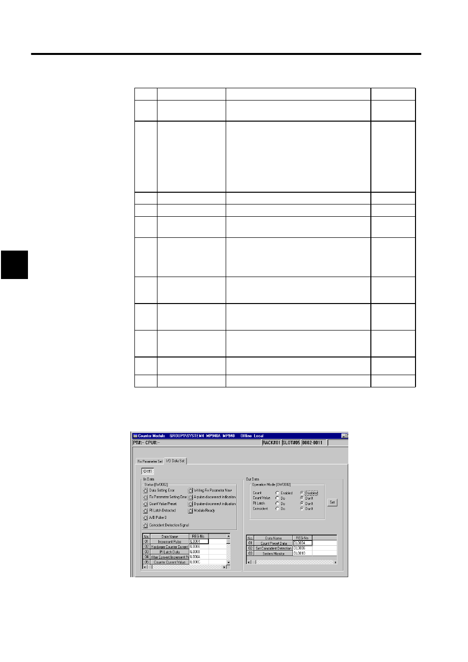
I/O Data Set Tab Page
Click the I/O Data Set Tab.
1. Channel Number
The channel number display is fixed at CH#1.
2
A/B Pulse Signal
Polar
The polarity of the A/B pulse
Positive: 0, Negative: 1
0
3
Pulse Count
0: Signed (multiply x1)
1: Signed (multiply x2)
2: Up/Down (multiply x1)
3: Up/Down (multiply x2)
4: A/B pulse (multiply x1)
5: A/B pulse (multiply x2)
6: A/B pulse (multiply x4)
6
4
Counter Mode
Always set to Reversible Counter.
-
5
PI Latch Detection
Always set to PI Latch.
-
6
Coincident Detec-
tion
Use of coincident detection
Unuse: 0, Use: 1
0
7
Coincident IRQ
Use of coincident interrupt
Unuse: 0, Use: 1
Coincident IRQ is valid only when Coincident
Detection above is set to “1.”
0
8
Select the use of
electronic
gear
Use of gear ratio
Unuse: 0, Use: 1
0
9
Pulse number per
one cycle of
the encoder
1 to 65535
2048
10
Moving amount per
one cycle of
the machine
1 to 2-1
10000
11
Encoder side gear
ratio
1 to 65535
1
12
Gear ratio (load)
1 to 65535
1
No.
Setting Item
Details
Default