Setting parallel connections – Yaskawa MP900 Series Machine Controller for Standard Operation User Manual
Page 406
7.3 Creating Ladder Logic Programs
7-39
7
4. Enter the relay number.
1 The mnemonic for a connection point, a period (.), can be used at step 2. to display a connection point.
2 Once step 4. has been completed, the input position for the next instruction will be on the new line after
the connection point. If a branch has been designated previously, the next instruction will be entered
from the branch position, and if not, the next instruction will be entered from the power line.
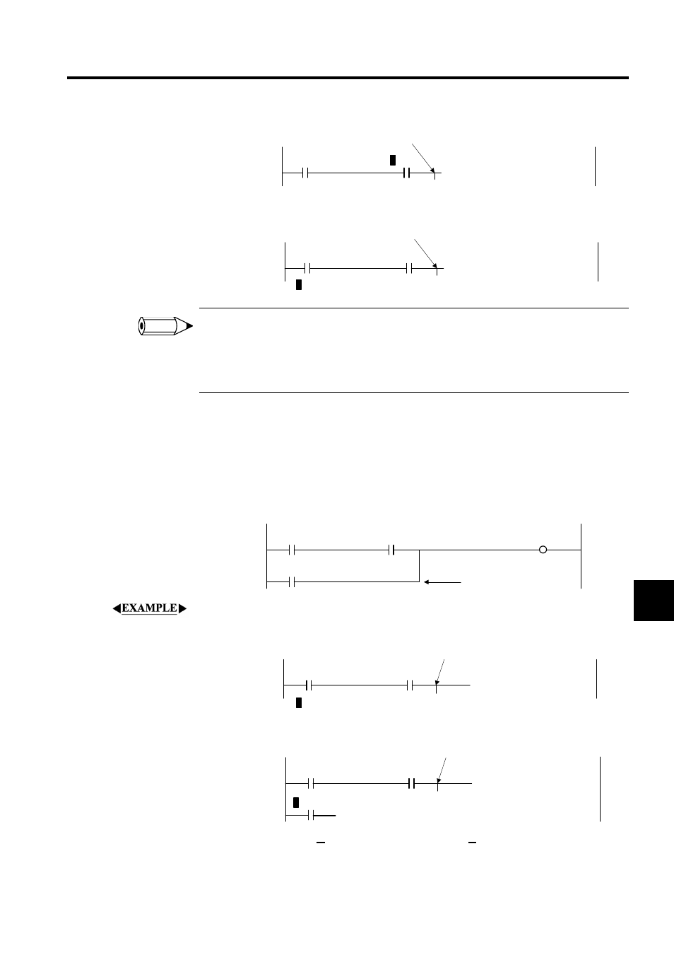
Setting Parallel Connections
As shown in the following diagram, the connection point specified above is connected to the
right side of the current instruction input position. A connection point must be specified first
to enable connection.
The procedure to set the parallel connection shown in the above diagram is outlined below.
1. Designate the connection point as shown below.
2. Select the N.O. CONTACT instruction.
3. Select Command (O), Relay (R) and then Connect (C) from the programming menus.
1 0000
IB00000
Connection Point
1 0000
IB00000
IB00001
Connection Point
INFO
1 0000
IB00000
OB00000
1 0002
IB00002
IB00001
Connection point
1 0000
IB00000
IB00001
Connection point
1 0002
1 0000
IB00000
IB00001
Connection point