Yaskawa MP2200 Machine Controller User Manual
Page 139
4.3 SVB-01 Module Parameter Details
4-19
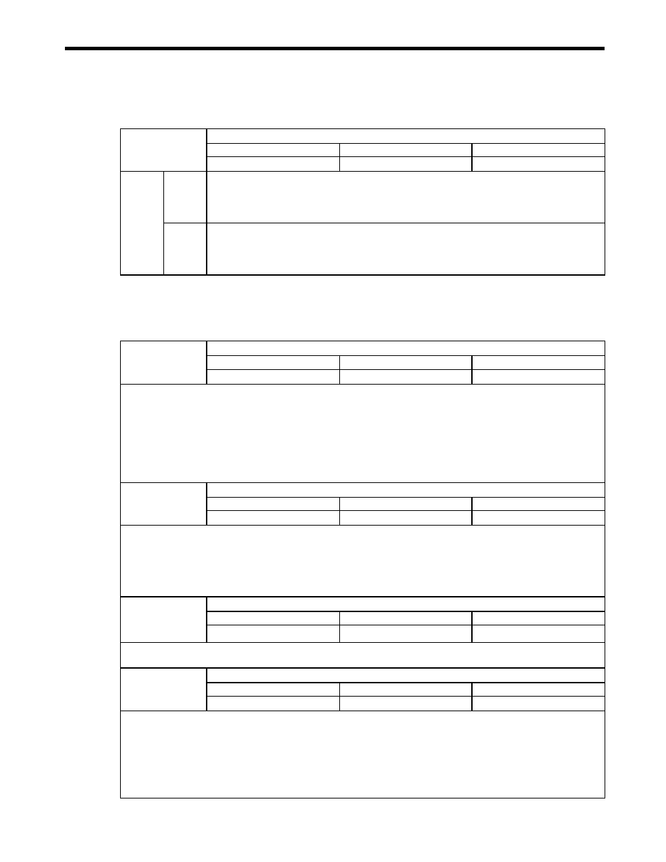
( 3 ) Function Selection 2
( 4 ) Reference Unit Settings
No. 2
Function Selection 2
Setting Range
Setting Unit
Default Value
−
−
0000H
No. 2
Bit 0
Communication Error Mask
Masks MECHATROLINK communication errors detected at the MP2200/MP2300.
0: Disabled (default)
1: Enabled
Bit 1
WDT Error Mask
Masks MECHATROLINK watchdog timeout errors detected at the MP2200/MP2300.
0: Disabled (default)
1: Enabled
No. 4
Command Unit
Setting Range
Setting Unit
Default Value
0 to 3
−
0
Set the unit for the reference that is input.
The minimum reference unit is determined by this parameter and, the Number of Decimal Places (fixed parameter 5). If pulse is
selected, the Gear Ratio (fixed parameters 8 and 9) will be disabled.
Refer to ( 1 ) Reference Unit in 4.5 Example of Setting Motion Parameters for the Machine for details.
0: pulse (electronic gear disabled)
1: mm
2: deg
3: inch
No. 5
Number of Decimal Places
Setting Range
Setting Unit
Default Value
0 to 5
−
3
Set the number of places to the right of the decimal point in input references.
The minimum reference unit is determined by this parameter and the Command Unit (fixed parameter 4).
Example: If Command Unit = mm and Number of Decimal Places = 3
Then, a reference unit of 1 = 0.001 mm
The setting of this parameter is disabled if the Command Unit is set to pulse in fixed parameter 4.
Refer to ( 1 ) Reference Unit in 4.5 Example of Setting Motion Parameters for the Machine for details.
No. 6
Command Unit per Revolution
Setting Range
Setting Unit
Default Value
1 to 2
31
−1
Reference unit
10000
Specify the amount of travel in the load as the number of reference units for each turn of the load shaft.
Refer to ( 1 ) Reference Unit in 4.5 Example of Setting Motion Parameters for the Machine for details.
No. 8
Gear Ratio [MOTOR]
Setting Range
Setting Unit
Default Value
1 to 65535
rev (revolutions)
1
Set the gear ratio between the motor and the load.
The following two values are set for a configuration in which the load shaft will turn n times in response to m turns of the motor
shaft.
• Gear ratio at Servomotor: m
• Gear ratio at load: n
The setting of this parameter is disabled if the Command Unit (Reference Unit) is set to pulse in fixed parameter 4.
Refer to ( 2 ) Electronic Gear in 4.5 Example of Setting Motion Parameters for the Machine for details.