Example – Yaskawa MP2200 Machine Controller User Manual
Page 410

7 Absolute Position Detection
7.3.2 Infinite Length Axis
7-26
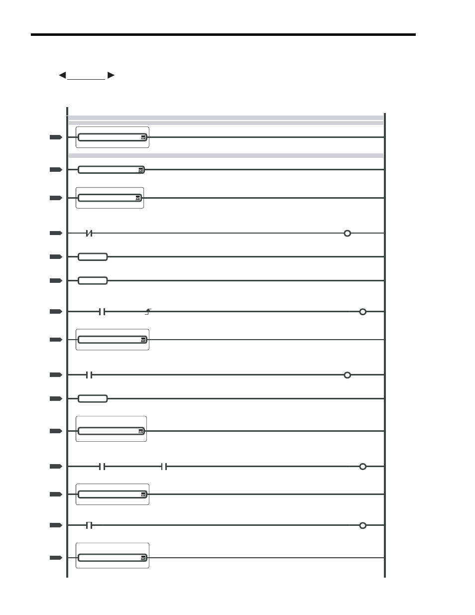
The following programming example (ladder program) is for the flowchart shown on the previous
page. The axis used here is axis 1 of circuit number 1. Change the motion parameter register number
if the circuit and axis numbers are different.
EXAMPLE
Absolute system infinite length axis: Axis 1 Leading address of toggle buffer: MW30000
ON for only the first scan after high-speed scan is started.
IF
SB000001!=true
H10
0000
0000
NL-1
SVCRDY (Operation Ready)
IF
IB80000!=true
0001
0001
NL-2
IF
IL8004!=0000
0002
0002
NL-3
SB000004
Position Information SAVE bit
MB300003
0003
0003
NL-4
END_IF
0004
0005
NL-3
END_IF
0005
0006
NL-2
Zero Point Setting Completed Flag
IB800C5
DB000201
DB000202
0006
0007
NL-2
IF
DB000202==true
0007
0010
NL-2
SB000004
Position Information SAVE bit
MB300003
0008
0011
NL-3
END_IF
0009
0013
NL-2
IF
IB80022!=true
0010
0014
NL-2
Zero Point Setting Completed Flag
IB800C5
Position Information SAVE bit
MB300003
DB000203
0011
0015
NL-3
IF
DB000203==true
0012
0018
NL-3
SB000004
MB300000
0013
0019
NL-4
Toggle Buffer Selection Flag
IF
MB300001==true
0014
0021
NL-4
P00001 H10 Main Program
Motion fixed parameters setting
error
(continued on next page)