2 led indicators and switch settings, 2 led, 2 led indicators and switch settings -6 – Yaskawa MP2200 Machine Controller User Manual
Page 52: 1 ) external appearance, 2 ) indicators
2 Module Specifications and Connections
2.1.2 LED Indicators and Switch Settings
2-6
■
Transmission Distance and Maximum No. of Slave Stations
* The values in parentheses apply when a JEPMC-REP2000 Repeater is used.
A JEPMC-REP2000 Repeater must be used if 17 or more slave stations are connected when
using MECHATROLINK-II communication.
2.1.2 LED Indicators and Switch Settings
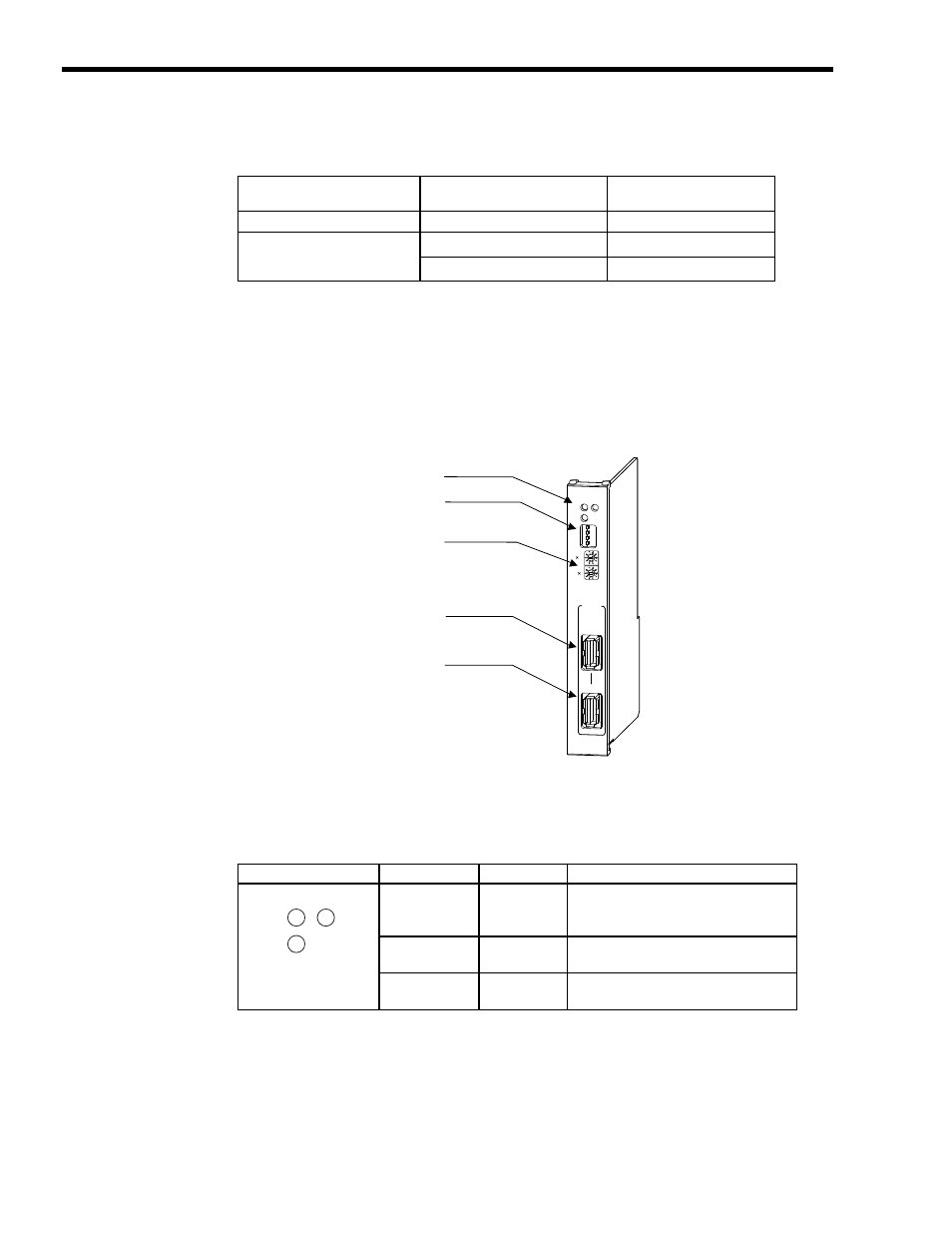
( 1 ) External Appearance
The following figure shows the external appearance of the SVB-01 Module.
( 2 ) Indicators
The following table shows the indicators that show the operating status of the SVB-01 Module and
error information.
Communication Method
Transmission Distance (Total
Network Length)
Maximum Number of Slave
Stations
MECHATROLINK-I
50 m
14
MECHATROLINK-II
30 m
16 (21)
*
50 m
15 (21)
*
SVB-01
TX
ERR
RUN
SPD
SIZE
M/S
ON
OFF
10
1
M-I/II
CN1
CN2
LED indicators
Rotary switches
(station address setting)
DIP switch
MECHATROLINK
connector
MECHATROLINK
connector
Indicators
Indicator Name
Color
Significance when Lit
RUN Green
Lights during normal operation of the
microprocessor used for control.
Not lit if an error has occurred.
ERR Red
Lights/blinks for failures.
Not lit during normal operation.
TX Green
MECHATROLINK transmission in
progress
RUN
TX
ERR