2 error detection, 1 svb-01 module led indicators, 1 svb – Yaskawa MP2200 Machine Controller User Manual
Page 512: 2 error detection -26, 1 svb-01 module led indicators -26
10 Troubleshooting
10.2.1 SVB-01 Module LED Indicators
10-26
10.2 Error Detection
10.2.1 SVB-01 Module LED Indicators
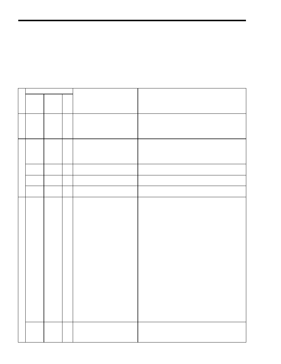
The following table shows how to use the LED indicators to determine the operating status of the
SVB-01 Module, as well as relevant error information when the LED indicator status indicates an
error.
Cl
as
si
ficati
on
LED Indicator
Indicator Details
Meaning
RUN
ERR
TX
Initi
ali
zation
Lit
Not lit
Lit
Status when power is turned ON
This is the status just after the Module's power supply is turned
ON.
The ERR Indicator is turned OFF during initialization.
A boot error occurred if this LED status does not change.
The SVB-01 firmware must be overwritten if a boot error occurs.
N
ormal opera
tion
Lit
Lit
Lit
Undefined status
This status indicates that the Module has not been registered in the
Module Definitions.
When the Module will be used, it must be registered in the Module
Definitions, the definitions must be transferred, and I/O must be
allocated.
Not lit
Lit
Not
lit
Normal operation
The Module is operating normally and MECHATROLINK
communication is established.
Not lit
Lit
Lit
Normal operation
(waiting for connection)
When the Module is set as a Slave, this LED status indicates that
communication has not been established with the Master.
Blinking
Lit
Not
lit
CPU STOP
Indicates that the CPU is stopped. The LED status will return to
normal operating status when the CPU starts to run.
Err
ors
Not lit
Not lit
Not
lit
■
Master Mode:
Servo axis error
• Warning occurred. (See IL02.)
• Alarm occurred. (See IL04.)
• Command Error End status
(IB093 ON and IB0B3 ON)
Note:
The LED Indicators will be OFF when
these conditions occur in any axis.
■
Slave Mode:
MECHATROLINK Communication
Error
The meaning of this LED status is different in Master Mode and
Slave Mode.
■
Master Mode
This LED status indicates that one of the listed errors occurred in
any Servo axis.
Check the corresponding parameters to determine which error
occurred.
• Any kind of warning may cause this condition. The bits in
IL02 indicate the cause of the warning, so it is necessary to
identify the cause of the warning, eliminate the cause, and
perform an Alarm Reset.
• Any kind of alarm may cause this condition.The bits in IL04
indicate the cause of the alarm, so it is necessary to identify the
cause of the alarm, eliminate the cause, and perform an Alarm
Reset.
• If the Module is in Command Error End status, an error occurred
during execution of a motion command or motion subcommand.
For example, a command will end in an error if an out-of-range
command is applied. Clear the command in OW08 or
OW0A.
■
Slave Mode
This LED status indicates that an error occurred in
MECHATROLINK communication.
Check the MECHATROLINK cable connections.
Not lit
Not lit
Lit
Master Communication Interrupted
In Slave Mode, this LED status indicates that communication from
the Master have stopped.
Check the Master's status and the MECHATROLINK cable
connections.