2 ) control block diagram for torque control – Yaskawa MP2200 Machine Controller User Manual
Page 374
6 Control Block Diagrams
6.1.3 Torque Control
6-18
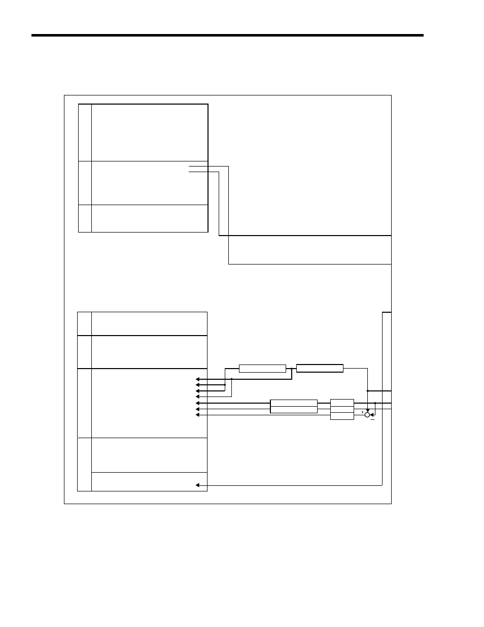
( 2 ) Control Block Diagram for Torque Control
MP2200
SVB-01
OW
00
OW
03
OW
08
OW
09
OW
0A
OL
0C
OL
0E
OL
48
OL
4A
OL
4C
IW
00
IL
02
IL
04
IW
08
IW
09
IW
0A
IW
0B
IW
0C
IL
0E
IL
10
IL
12
IL
14
IL
16
IL
18
IL
1A
IL
1C
IL
1E
IL
20
IW
2C
IW
2D
IW
2E
IW
2F
IW
30
IL
40
IL
42
RUN Commands
Function 1
Motion Command
Motion Command Options
Motion Subcommand
Torque Reference
Speed Limit at Torque Reference
Zero Point Offset
Work Coordinate System Offset
Preset Data of POSMAX Turn
Drive Status
Warning
Alarm
Servo Command Type Response
Servo Module Command Status
Motion Subcommand Response Code
Motion Subcommand Status
Position Management Status
Machine Coordinate Target Position (TPOS)
Target Position (CPOS)
Machine Coordinate System Position (MPOS)
32-bit Coordinate System Position (DPOS)
Machine Coordinate Feedback Position (APOS)
Machine Coordinate Latch Position (LPOS)
Position Error (PERR)
Target Position Difference Monitor
POSMAX Number of Turns
Speed Reference Output Monitor
Network Servo Status
Servo Alarm Code
Network Servo I/O Monitor
Network Servo User Monitor Information
Servo User Monitor 2
Feedback Speed
Torque (Thrust) Reference Monitor
POSMAX processing
Electronic gear
POSMAX processing
Electronic gear
POSMAX processing
Electronic gear
Run Settings
Torque Reference
Coordinates
Run
Information
Motion Command
Information
Position Information
SER
VOP
ACK
Information
Follow-up processing
(continued on next page)