2 sva-01 module led indicators, 2 sv, 2 sva-01 module led indicators -28 – Yaskawa MP2200 Machine Controller User Manual
Page 514
10 Troubleshooting
10.2.2 SVA-01 Module LED Indicators
10-28
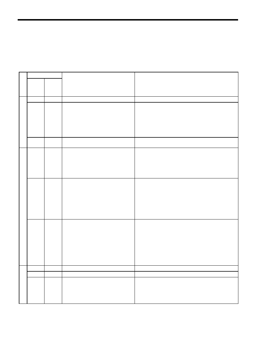
10.2.2 SVA-01 Module LED Indicators
The following table shows how to use the LED indicators to determine the operating status of the
SVA-01 Module, as well as relevant error information when the LED indicator status indicates an
error.
Classification
Indicator Name
Indicator Details
Meaning
RUN
ERR
Normal
o
perat
io
n
Lit
Lit
Hardware reset status
Indicates hardware reset.
Lit
Not lit
Initialization
• The LEDs are normally this status for about 1 to 6 seconds after
turning ON the power or resetting the Module. When an
Absolute Encoder is selected in fixed parameter 30, this status
will continue for 30 seconds per axis if there is an error in the
interface with the Absolute Encoder.
• This status will also continue indefinitely if there is an infinite
loop in Drawing A.
Not lit
Lit
Normal operating condition
This status is entered when STOP operation is performed from a
switch or the MPE720.
Er
ror
s
Not lit
Blinking
A CPU data transmission error has been
detected.
2: Watchdog timer over error
3: Synchronization error
Note: The number indicates how many times
the ERR LED will flash.
When a CPU Module error is detected, the RUN LED will be lit
and the ERR LED will blink.
Blinking
Blinking
Hardware error
(Number of LED blinks indicates error type.)
2: ROM diagnostic error
3: RAM diagnostic error
4: CPU function diagnostic error
5: CPU function diagnostic error
6: Shared memory diagnostic error
7: JL-045 diagnostic error
The RUN and ERR LEDs will blink when there is a self-diagnosis
failure.
Lit
Blinking
Hardware error
(Number of LED blinks indicates error type.)
3: Address error (read) exception
4: Address error (write) exception
5: FPU exception error
6: Illegal general command
7: Illegal slot command
8: General FPU inhibited error
9: Slot FPU inhibited error
The ERR indicator will blink when an exception error has
occurred.
Wa
rn
in
g
Blinking
Lit
CPU stopped
The RUN LED will blink.
Lit
Lit
Undefined status
−
Not lit
Not lit
Alarm or warning occurred.
Check the contents of the following monitoring parameters.
IL02: Warning
IL04: Alarm
IW09, bit3: Motion Command Error End
IW0B, bit3: Motion Subcommand Error End