4 ) analog servo alarm list – Yaskawa MP2200 Machine Controller User Manual
Page 496
10 Troubleshooting
10.1.2 Motion Error Details and Corrections
10-10
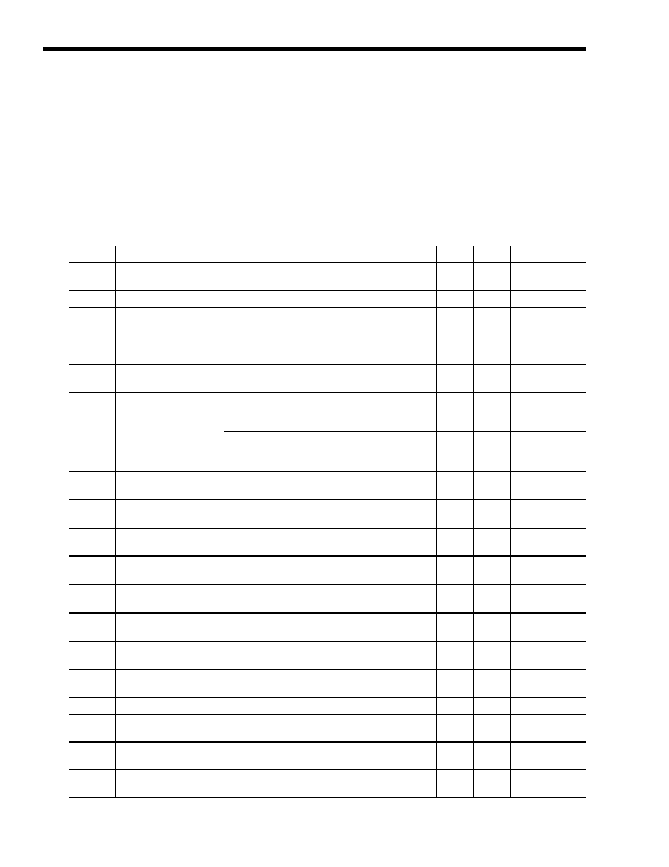
( 4 ) Analog Servo Alarm List
The Servo Driver Error Flag (IL04, bit 0) turns ON when an alarm has occurred in a
SERVOPACK connected to the SVA-01 Module.
The content of the alarm can be confirmed by connecting a Digital Operator to the SERVOPACK.
The following tables show the alarms that can occur in the SGDA, SGDB, SGDM, SGDH, and
SGDS SERVOPACKs.
[ a ] Alarm List for the SGDA, SGDB, SGDM, and SGDH SERVOPACKs
Table 10.1 Analog Servo Alarm List (A)
Code
Alarm Name
Alarm Content
SGDA
SGDB
SGDM
SGDH
A.00
Absolute Value Data
Error
Absolute data cannot be received or the received
absolute data is invalid.
{
{
×
×
A.02
Parameter Corrupted
A parameter checksum error was detected.
{
{
{
{
A.03
Main Circuit Detector
Error
There was an error in the power circuit's detection
data.
×
×
{
{
A.04
Parameter Setting
Error
A parameter value setting exceeded the allowed
setting range.
{
{
{
{
A.05
Combination Error
The motor and SERVOPACK capacity settings are
incompatible.
×
×
{
{
A.09
Divider Setting Error
An invalid Divider Setting (Pn212) was set (between
increments) or the setting exceeds the connected
Encoder's resolution.
×
×
{
×
When a linear motor is connected, the setting exceeds
the maximum dividing ration (Pn281), which was
calculated from the linear motor's maximum speed.
×
×
{
×
A.0A
Encoder Type
Mismatch
A serial encoder has been mounted that is not
supported by the
Σ-II.
×
×
{
×
A.10
Overcurrent or Heat
Sink Overheat
There was an overcurrent in the power transistor.
The heat sink overheated (SGDM).
{
{
{
{
A.30
Regeneration Error
An error occurred in the regeneration processing
circuit.
{
{
{
{
A.31
Position Error Pulse
Overflow
The position error pulses exceeded the “Overflow”
limit set in the parameters.
{
{
×
×
A.32
Regeneration
Overload
The regenerative energy exceeds the regenerative
resistor's capacity.
×
×
{
{
A.33
Main Circuit Wiring
Error
The power supply method used to supply the main
circuit does not match the setting in parameter Pn001.
×
×
{
{
A.40
Overvoltage
The power supply voltage to the main circuit is
excessively high.
{
{
{
{
A.41
Undervoltage
The power supply voltage to the main circuit is too
low.
×
×
{
{
A.51
Overspeed
The motor's speed is too high.
{
{
{
{
A.70
Overload
The torque exceeded the rated torque (high or low
load).
{
×
×
×
A.71
Overload (High Load)
The torque significantly exceeded the rated torque for
several seconds to several dozen seconds.
×
{
{
{
A.72
Overload (Low Load)
The motor is operating continuously at a torque
exceeding the rated torque.
×
{
{
{