2 ) control block diagram for speed control – Yaskawa MP2200 Machine Controller User Manual
Page 380
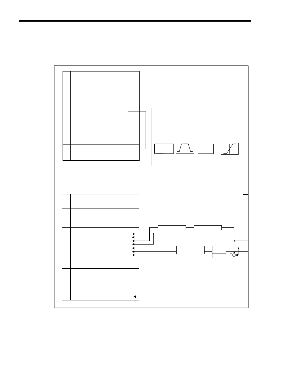
6 Control Block Diagrams
6.1.4 Speed Control
6-24
( 2 ) Control Block Diagram for Speed Control
MP2200
SVB-01
OW
00
OW
03
OW
08
OW
09
OW
0A
OL
10
OL
14
OL
36
OL
38
OW
3A
OL
48
OL
4A
OL
4C
IW
00
IL
02
IL
04
IW
08
IW
09
IW
0A
IW
0B
IW
0C
IL
0E
IL
10
IL
12
IL
14
IL
16
IL
18
IL
1A
IL
1C
IL
1E
IL
20
IW
2C
IW
2D
IW
2E
IW
2F
IW
30
IL
40
IL
42
OW
3A
Acceleration/
deceleration
processing
Acceleration: OL
36
Deceleration: OL
38
RUN Commands
Function 1
Motion Command
Motion Command Options
Motion Subcommand
Speed Reference
Positive Side Limiting Torque
Setting at the Speed Reference
Linear Acceleration Time
Linear Deceleration Time
S-curve Acceleration Time
Zero Point Offset
Work Coordinate System Offset
Preset Data of POSMAX Turn
Drive Status
Warning
Alarm
Servo Command Type Response
Servo Module Command Status
Motion Subcommand Response Code
Motion Subcommand Status
Position Management Status
Machine Coordinate Target Position (TPOS)
Target Position (CPOS)
Machine Coordinate System Position (MPOS)
32-bit Coordinate System Position (DPOS)
Machine Coordinate Feedback Position (APOS)
Machine Coordinate Latch Position (LPOS)
Position Error (PERR)
Target Position Difference Monitor
POSMAX Number of Turns
Speed Reference Output Monitor
Network Servo Status
Servo Alarm Code
Network Servo I/O Monitor
Network Servo User Monitor Information
Servo User Monitor 2
Feedback Speed
POSMAX processing
Electronic gear
POSMAX processing
Electronic gear
POSMAX processing
Electronic gear
Filter
Limiter fixed.
No parameter
Override
processing
Run Settings
Speed Reference
Acceleration/
Deceleration
Coordinates
Run
Information
Motion Command
Information
Position Information
SER
VOP
ACK
Information
Torque (Thrust) Reference Monitor
(continued on next page)
Follow-up processing
OL
18 Speed Override