1 list of motion modules, 1 list of, 1 list of motion modules -2 – Yaskawa MP2200 Machine Controller User Manual
Page 36
1 Motion Module Overview
1-2
1.1 List of Motion Modules
The Motion Modules that can be used with the MP2200/MP2300 are listed below.
Module Description
SVB-01 Module
SVA-01 Module
SVR Module
Name
SVB-01
SVA-01
SVR
Model Number
JAPMC-MC2310
JAPMC-MC2300
−
Module Appearance
Virtual Motion Module
Refer to 1.4 Virtual Motion
Module (SVR) Overview.
Interface
MECHATROLINK-I/II
communication
Analog outputs and feedback pulse
inputs
−
Maximum Number of
Controlled Axes/Module
Up to 16 axes
Up to 2 axes
Up to 16 axes
Maximum Number of
Modules/Machine
Controller
MP2300: 2 Modules
MP2300: 2 Modules
1
MP2200: 16 Modules
MP2200: 16 Modules
Con
trol
S
peci
fica
tions
PTP Control
Linear, rotating, and infinite-length
Linear, rotating, and infinite-length
Linear, rotating, and infinite-
length
Interpolation
Up to 16 linear axes, 2 circular axes,
and 3 helical axes
Up to 16 linear axes (with the
MP2200), 2 circular axes, and 3
helical axes
Up to 16 linear axes, 2 circular
axes, and 3 helical axes
Speed Reference
Output
Up to 256 axes
(MECHATROLINK-II, for
MP2200)
Up to 32 axes (with the MP2200)
Up to 16 axes
(MECHATROLINK-II)
Torque Reference
Output
Up to 256 axes
(MECHATROLINK-III, for
MP2200)
Up to 32 axes (with the MP2200)
Up to 16 axes
(MECHATROLINK-II)
Position Control
Positioning, External Positioning,
Zero Point Return, Interpolation,
Interpolation with Position
Detection, JOG operation, and
STEP operation
Same as at left.
Same as at left.
Phase Control
Up to 256 axes
Up to 32 axes (with the MP2200)
Up to 16 axes
Self-configuration
Automatically sets data for Module
and Slave devices.
Automatic allocation by Module is
supported.
−
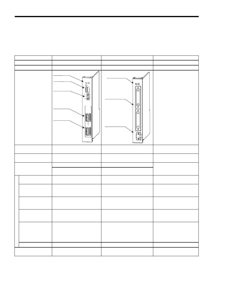
SVB-01
TX
ERR
RUN
SPD
SIZE
M/S
ON
OFF
10
1
M-I/II
CN1
CN2
LED indicators
Switch (station
address setting)
Switch
MECHATROLINK
Connector
MECHATROLINK
Connector
SVA-01
LED indicators
Servo connectors
24-V input connector
RUN
CH1
CH2
DC IN
ON
+24V
ERR