Main circuit wiring, Factory recommended branch circuit protection, Main circuit terminal functions – Yaskawa iQpump1000 AC Drive Quick Start User Manual
Page 131: 6 main circuit wiring
3.6 Main Circuit Wiring
This section describes the functions, specifications, and procedures required to safely and properly wire the main circuit in
the drive.
NOTICE: Do not solder the ends of wire connections to the drive. Soldered wiring connections can loosen over time. Improper wiring practices
could result in drive malfunction due to loose terminal connections.
NOTICE: Do not switch the drive input to start or stop the motor. Frequently switching the drive on and off shortens the life of the DC bus
charge circuit and the DC bus capacitors, and can cause premature drive failures. For the full performance life, refrain from switching the
drive on and off more than once every 30 minutes.
Note:
Refer to Single-Phase Derating on page 317
for applying and protecting the drive when using single-phase input power.
Refer to Factory Recommended Branch Circuit Protection for UL Compliance on page 460
for details on fuse selection.
u
Factory Recommended Branch Circuit Protection
WARNING! Fire Hazard. Install adequate branch circuit protection according to applicable local codes and this manual. Failure to comply
could result in fire and damage to the drive or injury to personnel. The device is suitable for use on a circuit capable of delivering not more
than 100,000 RMS symmetrical amperes, 240 Vac (200 V class) and 480 Vac (400 V class), when protected by branch circuit protection
devices specified in this manual.
Branch circuit protection shall be provided by any of the following: Non-time delay Class J, T, or CC fuses sized at 300% of the drive input
rating, or Time delay Class J, T, or CC fuses sized at 175% of the drive input rating, or MCCB sized at 200% maximum of the drive input
rating.
Yaskawa recommends installing branch circuit protection according to maintain compliance with UL508C. Semiconductor
protective type fuses are preferred. Alternate branch circuit protection devices are also listed in this manual.
Recommended Branch Circuit Protection on page 448
for details.
u
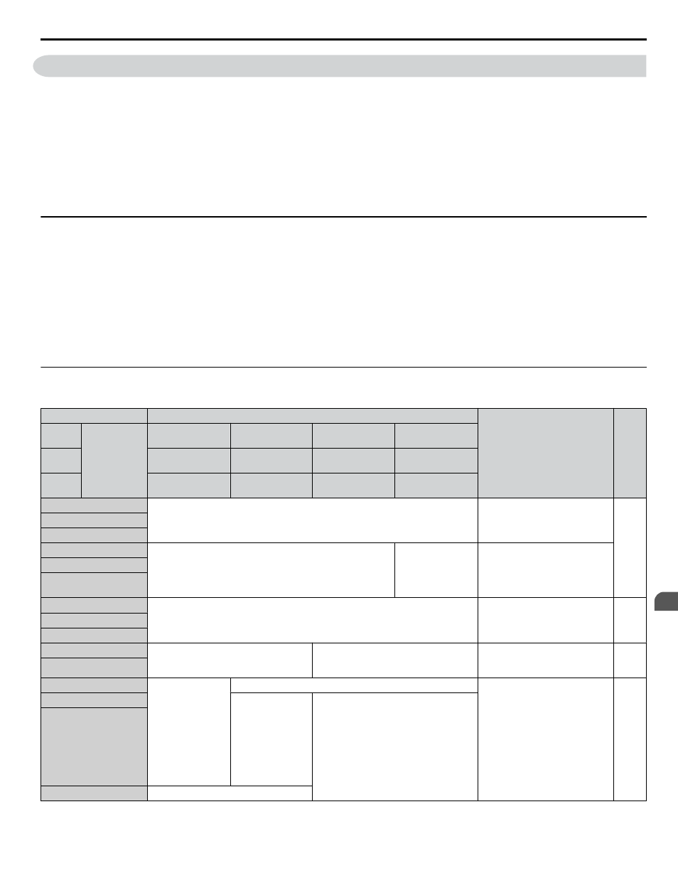
Main Circuit Terminal Functions
Table 3.1 Main Circuit Terminal Functions
Terminal
Type
Function
Page
200 V
Class
Drive Model
2A0004 to
2A0081
2A0110, 2A0138
2A0169 to
2A0415
–
400 V
Class
4A0002 to
4A0044
4A0058, 4A0072
4A0088 to
4A0675
4A0930, 4A1200
600 V
Class
5A0003 to
5A0032
5A0041, 5A0052
5A0062 to
5A0242
–
R/L1
Main circuit power supply input
Connects line power to the drive
S/L2
T/L3
R1-L11
Not available
Main circuit power
supply input
Connects line power to the drive
Remove the shorting bars
connecting R/L1-R1/L11, S/L2-
S1/L21, T/L3-T1/L31 when
using 12-phase rectification.
S1-L21
T1-L31
U/T1
Drive output
Connects to the motor
V/T2
W/T3
B1
Braking resistor
Not available
Available for connecting a
braking resistor or a braking
resistor unit option
–
B2
⊕2
• DC link choke
connection
(
⊕1, ⊕2)
(remove the
shorting bar
between
⊕1 and ⊕2)
• DC power
supply input
(
⊕1, ⊖)
Not available
For connecting:
• the drive to a DC power supply
• dynamic braking options
• a DC link choke
–
⊕1
DC power supply
input
(
⊕1, ⊖)
• DC power supply input (
⊕1, ⊖)
• Braking unit connection (
⊕3, ⊖)
⊖
⊕3
Not available
3.6 Main Circuit Wiring
YASKAWA TOEP YAIP1W 01B YASKAWA AC Drive - iQpump1000 Quick Start Guide
131
3
Electrical Installation