P1-11: high feedback level, P1-12: high feedback level fault delay time, P1-13: high feedback selection – Yaskawa iQpump1000 AC Drive Quick Start User Manual
Page 227
n
P1-11: High Feedback Level
Sets the level at which a High Feedback alarm or fault will occur. When the PID feedback rises above the P1-11 setting for
the time set in P1-12, the drive will respond based on the setting in P1-13.
No.
Parameter Name
Setting Range
Default
P1-11
High Feedback Level
0.0 to 6000.0
155.0 PSI
n
P1-12: High Feedback Level Fault Delay Time
Sets the delay time after which a Low Feedback alarm or fault will occur. When the PID feedback rises above the P1-11 setting
for the time set in P1-12, the drive will respond based on the setting in P1-13.
No.
Parameter Name
Setting Range
Default
P1-12
High Feedback Level Fault Delay Time
0 to 3600 s
5 s
n
P1-13: High Feedback Selection
Selects the drive response to a High Feedback condition. When the PID feedback rises above the P1-11 setting for the time
set in P1-12, the drive will respond based on the setting in P1-13.
No.
Parameter Name
Setting Range
Default
P1-13
High Feedback Selection
0 to 2
0
High feedback detection is enabled when:
• P1-11 > 0
• Run Command present, including sleep & timer operation (standard PID, b5-09 = 0)
• Drive is running in AUTO Mode, including feedback drop detection (inverse PID, b5-09 = 1).
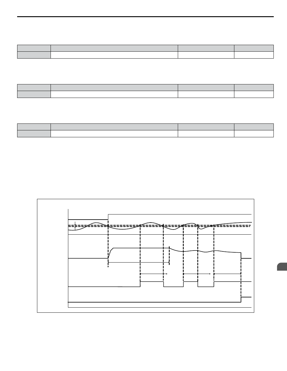
Setting 0: Fault
When feedback rises above the P1-11 for longer than the time set in P1-12, the drive will fault on the “HFB – High Feedback”
fault and coast to a stop.
The digital output programmed to “High Feedback” (H2-0o= 96) closes. The drive will also display the “High Feedback –
High FB Sensed” alarm. The digital output will remain closed until the fault is reset.
H igh F eedba ck D etection
Standa rd Acting PID (b5-09 = 0)
Ou tpu t
F requen cy
Au to R un
C omm an d
PID
F eedba ck
“H igh F eedba ck
H igh F B Sen sed ”
Alarm & D igital
Ou tpu t (H 2-0x = 96)
“HF B – H igh
F eedba ck” F au lt
D uring
Pre-C ha rge
P 1-11 – H igh F B Le vel
H igh F eedba ck Se l = F au lt (P1-13 = 0)
P1-12
H gh LVL F lt T m
P1-14
P1-12
H gh LVL F lt T m
P1-12
H gh LVL F lt T m
Figure 4.43 High Feedback Detection Standard PID
4.6 Basic iQpump Setup and Application Preset Parameters
YASKAWA TOEP YAIP1W 01B YASKAWA AC Drive - iQpump1000 Quick Start Guide
227
4
Start-Up Programming & Operation