Yaskawa iQpump1000 AC Drive Quick Start User Manual
Page 194
2.
Set the maximum Setpoint Boost in parameter (P3-10). This is set in the selected system units (PSI, etc.). When a
de-staging occurs and Setpoint Boost is to occur, the PI feedback level temporarily becomes the PI setpoint. Parameter
P3-10 limits how much the PI setpoint can be raised.
3.
Set the Setpoint Boost time in parameter P3-11. This sets how long the Setpoint Boost function will boost the PI
setpoint. After the P3-11 time expires, the PI setpoint will return to the Q1-01 setting.
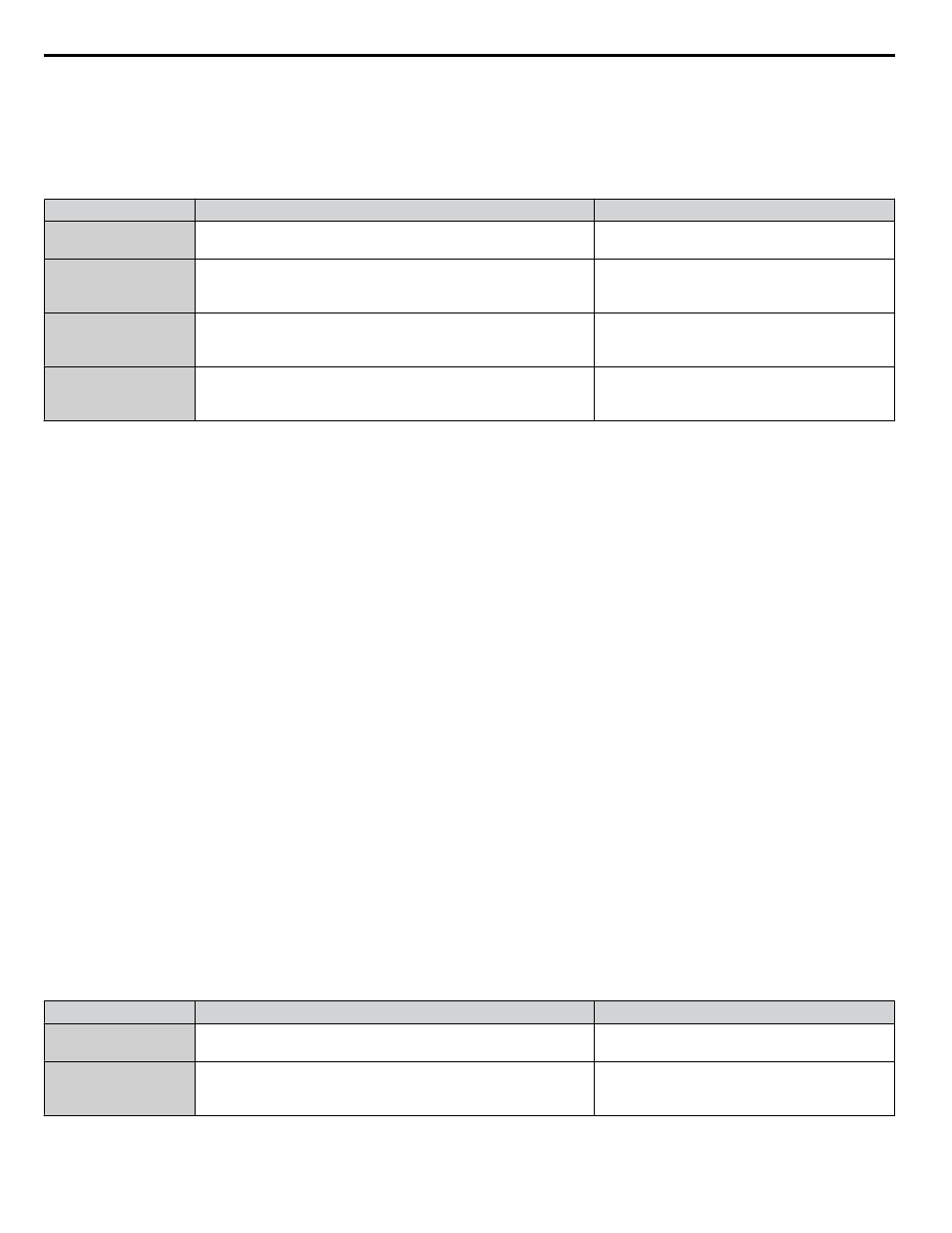
Related Parameters
No.
Parameter Name
Setting Values
b5-09
PID Output Level Selection
Default: 0
Range: 0, 1
P3-10
Setpoint Boost Maximum at De-Stage
Default: 0.0 PSI
Min.: -20.0
Max.: 20.0
P3-11
Setpoint Boost after De-Stage Time
Default: 5.0 s
Min.: 0.0
Max.: 60.0
Q1-01
PID Controller Setpoint 1
Default: 0.0
Min.: 0.0
Max.: 6000.0
n
Frequency Reduction after Lag Pump Staging
When a lag pump is staged (turned on), there can be a sudden increase in pressure in the system due to the pump staging on.
The Frequency Reduction function will dampen the shock load (pressure spike) to the system by temporarily limiting (lowering)
the drive controller output frequency during pump staging.
The function will limit the output frequency at time of de-staging for the time set in P3-07. When the P3-07 time expires, the
frequency limit is removed and the drive operates normally. The intention of the feature is to get the drive to begin decelerating
as soon as a pump is staged to limit the shock to the system, as the PI controller would tell the drive to decelerate in response
the staged on pump. It is not intended to regulate at the limited output frequency for an extended period of time.
Note:
1. When a lag pump is staged on, the drive will upper-limit the output frequency for the P3-07 (Frequency Reduction Time) setting. The
output frequency limit is determined by subtracting parameter P3-06 (Frequency Reduction at Staging) from parameter P3-03 (Max-
Multi Level). The default setting for P3-03 is 59.0 Hz, P3-06 is 0.0 PSI, and P3-07 is 0.0 sec.
2. The drive integrator will be limited to prevent wind-up and ensure a smooth transition back out of frequency limit.
3. Once the P3-07 time expires, the upper-limit will be removed and the drive will operate normally.
4. If the drive calls for de-staging a pump during the P3-07 time, the de-stage will be allowed to happen, and normal PI operation will
immediately resume.
5. If either P3-06 or P3-07 is set to zero, this feature will not operate.
While the output frequency is being controlled by the Frequency Reduction after Staging function, the drive will display the
message "Freq Reduction Active (P3-07)."
Start Up Procedure
1.
Set all other parameters required for the application such as PI control loop, sleep, motor, and I/O parameters.
to Vertical Turbine Controller (VTC) on page 188
for an example. However, this function can be used in conjunction
across a wide range of applications using a PI control process loop with multiple lag pumps that are staged and de-
staged.
2.
Set the amount of frequency reduction at staging in parameter P3-06. When a staging occurs, the output frequency
is limited to P3-03 – P3-06.
Example: If P3-03 = 59 Hz (default) and P3-06 is set to 5.0 Hz, the output frequency will be limited to 54 Hz.
3.
Set the Frequency Reduction time at staging in parameter P3-07. This sets how long the output frequency will be
limited during pump staging. After the P3-07 time expires, the PI controller will return to normal.
Related Parameters
No.
Parameter Name
Setting Values
b5-09
PID Output Level Selection
Default: 0
Range: 0, 1
P3-10
Setpoint Boost Maximum at De-Stage
Default: 0.0 PSI
Min.: -20.0
Max.: 20.0
4.5 iQpump Presets and Functions
194
YASKAWA TOEP YAIP1W 01B YASKAWA AC Drive - iQpump1000 Quick Start Guide