Yaskawa iQpump1000 AC Drive Quick Start User Manual
Page 182
important design characteristic is that the electrical conductors are installed by the manufacturer at the length specified
by the installer. This ensures that the manufacturer can calibrate the transducer to compensate for the voltage drop
across the conductor length. The maximum length for pressure transducer leads is 50 meters (164 feet) and beyond
that length the voltage drop will cause inaccurate feedback. It is common for wells to exceed this depth. Do not use
standard pressure transducer for level control. Select a range of depth that closely matches your application range.
One size does not fit all as depth calculations work with small changes in feedback. If the range is too large accuracy
will be compromised.
Proper Depth Transducer Characteristics:
Sealed element and electrical connections
Barometric compensation
Specified cable length calibrated by the manufacturer
Proper range, one that is close to applications actual operation
2.
Install Depth Sensing Pressure Transducer Down Hole. Since the feedback from the transducer is low voltage and
the output of the drive to the motor is a PWM waveform an effort should be made to keep the transducer leads as far
from the motor leads as possible. Given that space in the bore hole is at a premium this is a difficult task and connection
of the transducer shield drain wire is important. Many installers will set the transducer in its own plastic tubing with a
cap at the bottom end that the transducer can rest on. It is necessary to drill holes in the tubing at or close to the
bottom to allow water to flood the tube. This type of installation will help protect the transducer and connecting cable
from damage and allow it to be retrieved if necessary.
3.
Connect Level Transducer to the drive via Terminal A1. Most depth level transducers are current based feedback,
typically 4 to 20 mA. The A1 terminal of the drive is selectable for either voltage or current based pressure transducer
feedback. Most transducers in common use are current based (4 to 20 mA).
4.
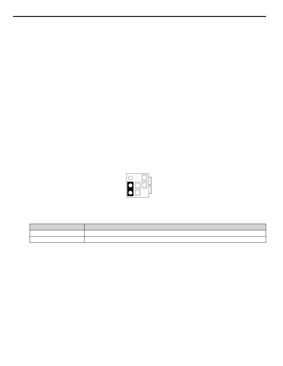
Set the drive to accept current based (4 to 20 mA) Feedback Set the A1 terminal of Jumper S1 to current type input
(I) as shown in
. Set parameter H3-01 to 2 (4 to 20 mA) for signal type on A1. Set parameter H3-02 to 23,
function of the A1 input, Well Level feedback
V
I
A1 A2 A3
Jumper S1
Figure 4.13 Terminal A1 Set to Current Input
Table 4.6 Jumper S1 Settings
Setting
Description
V (top position)
Voltage input (0 to 10 V Bipolar)
I (bottom position)
Current input (4 to 20 mA or 0 to 20 mA)
5.
Connect Standard Pressure Transducer to Terminal A2. Terminal A2 is designed to accept both current and voltage
based feedback devices and by default the drive is set to 4 to 20 mA input. Make sure to set all necessary parameters
for proper constant pressure regulation.
6.
Set parameter Q4-01 to 1 to enable the Well Draw Down Feature.
7.
Set Constant Pressure Setpoint in U1-01 or Q1-01. U1-01 is the only monitor which will change parameter values
without going to the program menu. Using this monitor, the setpoint can be changed while the drive is running. A
setpoint must be entered for the Well Draw Down feature to work properly.
8.
Enter the maximum value of the range of the transducer in PSI in parameter Q4-02 and the drive will automatically
scale associated parameters. The level transducer should display a specification for range (e.g., 0 to 50 PSI [115.4
feet]) 1 PSI = 2.308 ft.
9.
Set Well Level to be maintained in parameter Q4-03 This is the level (in feet) at which the drive will stop regulating
pressure and start maintaining level. If the water level rises above this level, the drive will automatically switch back
to pressure regulation.
10.
Set Well Level to Sleep in parameter Q4-04 When the well level reaches this level (in feet) and the sleep time set in
parameter Q4-05 expires, the drive will go to sleep and stop running the pump. The pump will remain in this state until
the well level reaches the wake level set in Q4-06..
4.5 iQpump Presets and Functions
182
YASKAWA TOEP YAIP1W 01B YASKAWA AC Drive - iQpump1000 Quick Start Guide