Yaskawa iQpump1000 AC Drive Quick Start User Manual
Page 186
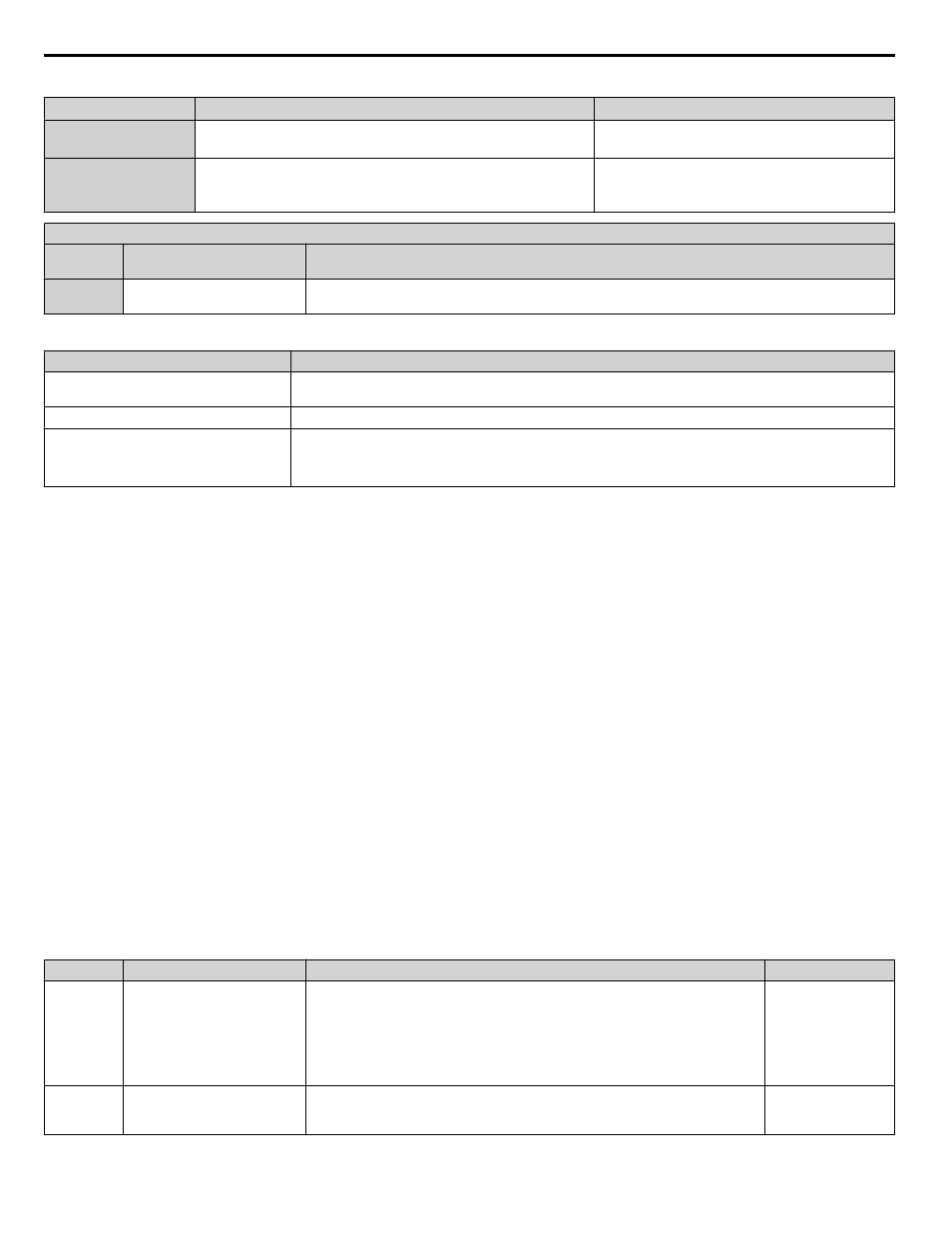
Related Parameters
No.
Parameter Name
Setting Values
Q3-01
Output Current Limit Select
Default: 0
Range: 0, 1
Q3-02
Current Limit
Default: 0.0 A
Min.: 0.0
Max.: 1000.0
H2 Multi-Function Digital Output Settings
H2-oo
Setting
Function
Description
89
Output 1 Limit
Closed: Drive output speed is being limited due to the output current limit or the single phase foldback
regulator.
The drive displays an alarm on the keypad when the drive is in output current limit.
HOA Keypad Display
Minor Fault Name
Current Limit
Foldback
Current Limit Foldback
Cause
Possible Solution
Drive output speed is being limited due to
the output current limit.
• Reduce the load.
• Verify setting of Q3-02.
• Change to a larger drive size.
n
Speed Follower Deceleration Time Switchover
The iQpump Speed Follower will attempt to match the speed of the Lead Drive after the Lag Drive Fixed Speed Delay.
Consider a scenario wherein the system needs help from an idle drive to maintain system pressure. When the idle drive is
called to run, the difference between the set-point and the feedback may be too small to make the drive accelerate faster. In
the case of a system is configured with these settings:
• Set for Lag Drive Speed Follower
• Add Pump method is Frequency Reference
• Frequency Reference setting close to the maximum frequency
The system will drop the speed after the Lag Drive Fixed Speed Delay expires in order to follow the output frequency of the
previously idle drive. This transition may cause unwanted pressure drops. A longer deceleration time will be activated on the
lag drives when the system switches the drive that is being followed. The longer deceleration time will be effective for a
programmable setting, after which, the regular deceleration time is used.
Functional Operation
If P9-05 = 3 (Follow Lead Spd), the lag drive will use the network information and the lead drive output speed as its frequency
reference. The lag drive's final speed reference is affected by (Lag Follower Gain P9-30) and then by (Lag Follower Bias
P9-31).
Lag Drive Speed = ( Lead Drive Speed x Lag Follower Gain ) + Lag Follower Bias
When P9-33 > 0.0 sec, an alternate deceleration time (Lag Follower Decel P9-32) is used when the drive switches from the
latched speed (Lag Fixed Delay P9-07) to the new Lead drive's output frequency. The deceleration time is active for the
duration set in (Lag Followr Dtim P9-33), and will switch back to the regular deceleration rates when it expires.
Note:
Parameter functionality stated below only applies when P1-01 = 3 (MEMOBUS Network)
Related Parameters
No.
Name
Description
Values
P9-05)
Lag Drive Mode
Determines the functionality of the lag drives.
0: Fixed speed. The drive runs at the P9-06 setting after the time set in P9-07
expires.
2: Turn off. The drive stops running when it switches to a lag drive after the time
set in P9-07 expires.
3: Follow Lead Speed. The drive will follow the speed of the current lead drive,
applying P9-30 gain and P9-31 bias.
Default: 0
Range: 0, 2, 3
P9-07
Lag Fixed Speed Delay
Specifies how long speed is latched before performing the function specified in
P9-05 when the drive changes from a lead to a lag.
Default: 5 s
Min.: 0
Max.: 1000
4.5 iQpump Presets and Functions
186
YASKAWA TOEP YAIP1W 01B YASKAWA AC Drive - iQpump1000 Quick Start Guide