Yaskawa iQpump1000 AC Drive Quick Start User Manual
Page 211
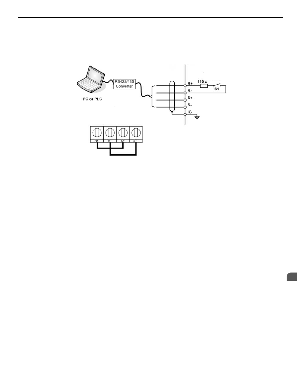
Setting 2: Serial Communications
This setting requires entering the frequency reference via the RS-485/422 serial communications port (control terminals R+,
R-, S+, S-).
To setup the drive to receive the “Auto Setpoint” from serial communication, set b1-01 to “2: Serial Com,” and connect the
RS-422/RS-485 serial communications cable to terminals R+, R-, S+, and S- on the control I/O terminal block. Refer to
to see the connection diagram using a PC to provide the auto setpoint reference to the drive.
Figure 5.4
RS-485 Communication Connection
Modbus RTU Communications
RS-422/RS-485
19.2 Kbps
Terminating
Resistor
Figure 4.30 PC or PLC Connection Diagram
Setting 3: Option card
This setting requires entering the frequency reference via an option board plugged into connector CN5-A on the drive control
board. Consult the option board manual for instructions on integrating the drive with the communication system.
Note:
If the frequency reference source is set for Option PCB (b1-01 = 3), but an option board is not installed, an oPE05 Operator Programming
Error will be displayed on the digital operator and the drive will not run.
To setup the drive to receive the “Auto Setpoint” for a network communication option card, set b1-01 to “3: Option PCB”,
and plug a supported communication option card into the drive control PCB. Consult the manual supplied with the option for
instructions on integrating the drive into the network system.
Refer to Option Installation on page 298
for a list of available drive network communication options.
Setting 4: Pulse Train Input
This setting requires a pulse train signal to terminal RP to provide the frequency reference. Follow the directions below to
verify that the pulse signal is working properly.
Verifying the Pulse Train is Working Properly
• Set b1-04 to 4 and set H6-01 to 0.
• Set the H6-02 to the pulse train frequency value that equals 100% of the frequency reference.
• Enter a pulse train signal to terminal RP and check for the correct frequency reference on the display.
Setting 5: Geothermal Mode
Refer to Geothermal Mode Application Preset on page 175
for details on how to use this function.
n
b1-02: Run Command Selection 1
Determines the Run command source 1 in AUTO Mode.
The drive comes factory programmed for Start and Stop from the keypad, but the user can program the drive to receive a Run
command from four different inputs: digital operator, terminals, serial communications, or an option PCB.
To set the drive to receive the Run command from the HOA keypad, set b1-02 to “0: Operator,” and the HAND key will be
used to provide the Run command to the drive.
To set the drive to receive the Run command from the external terminals, set b1-02 to “1: Terminals” and initiate an external
Run command by a contact closure between terminals S1 and SN.
Note:
Using the external terminals requires setting the drive to AUTO Mode by pressing the AUTO key.
4.6 Basic iQpump Setup and Application Preset Parameters
YASKAWA TOEP YAIP1W 01B YASKAWA AC Drive - iQpump1000 Quick Start Guide
211
4
Start-Up Programming & Operation