Selecting start/stop and speed method, B1-02 – Yaskawa iQpump1000 AC Drive Quick Start User Manual
Page 5
Step
4
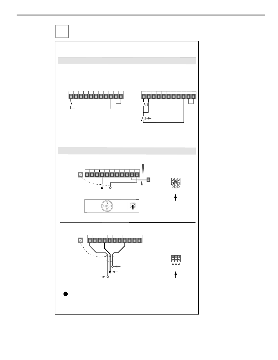
This step shows how to connect control wiring and feedback signal to the iQpump. Before
making any control connections MAKE SURE POWER TO THE iQpump IS TURNED
OFF! Next remove the terminal cover to gain access to the control terminals. (Step 1.)
SELECT START / STOP CONTROL METHOD
b1-02
NOTE: It is beyond the scope of this document to program the iQpump drive for network communication control.
Please refer to the refer to the iQpump1000 Quick Start Guide (Document No.
.
TOEPYAIP1W01) for this selection.
.
FEEDBACK SIGNAL WIRING (TRANSDUCER)
Wiring Diagram: 2-Wire Control
Run
(FWD)
Wiring Diagram: 3-Wire Control
Use for momentary contacts
Use for maintained contacts
User Terminals
User Terminals
Note: 3
rd
row of terminal board is shown here.
Link
Start
Switch
Stop
Switch
Normally
Open
Normally
Closed
Link
+V AC A1 A2 A3 FM AM AC RP AC 24V
Brown or Red: +Power (1)
Black: Output
4 – 20mA (2)
Cable
Shield
+V AC A1 A2 A3 FM AM AC RP AC 24V
2-Wire, 4-20mA Transducer
Cable
Type
DIN
Type
E(G)
S1 S2
S3 S4 S5 S6 S7 S8 SN SC SP
S1 S2
S3 S4 S5 S6 S7 S8 SN SC SP
Install link (AC-SN) when
using transducer.
SN
Factory Installed
To use 3-Wire Control first Initialize the
iQpump using parameter A1-03 = 3330
(Refer to the Quick Start Guide
TOEP YAIP 1W 01)
For use with 3-Wire, 0 – 10V Transducer
Brown or Red: +Power (1)
Black or White Output 0 – 10V (3)
Blue or Black Common Signal (2)
Important Note: Signal colors and numbering may vary depending
on feedback device used, please consult feedback device manual.
!
The iQpump is DEFAULT SETUP TO START /STOP FROM THE KEYPAD (digital operator).
If this is the preferred start/stop method then continue to the feedback signal connection
section. Please refer to the wiring diagram below to start/stop the iQpump using an external
switch or contact.
For use with 2-Wire, 4 – 20mA Transducer
(Factory Default)
E(G)
(Factory Default)
Jumper located
inside the drive on
the terminal board
Note: 2
nd
row of terminal
board is shown here.
A1 A3
A2
V
I
Set Jumper to use 0 – 10V
Transducer
Jumper located
inside the drive on
the terminal board
Note: 2
nd
row of terminal
board is shown here.
A1 A3
A2
V
I
3-Wire, 0-10V Transducer
Selecting Start/Stop and Speed Method
YASKAWA TOEP YAIP1W 01B YASKAWA AC Drive - iQpump1000 Quick Start Guide
5