Yaskawa iQpump1000 AC Drive Quick Start User Manual
Page 183
11.
Set Wake Level in parameter Q4-06. When the well level has reached this level (in feet) and the on-delay timer set
in Q4-07 expires, the drive will automatically start running again. Set this level should to a value greater than Q4-03
(Maintain Level) so the drive will automatically go to pressure regulation mode.
12.
Set the Minimum Pump Speed while in Level Control in parameter Q4-08 Set this speed at a level which ensures that
the pump is moving water out of the well. If it is set to a speed where no water is moving, the PI regulator may not
drive the well level to the sleep level and cause damage to the pump or motor. This speed is only used in Level Control
Mode but the actual minimum speed in Level Mode will be the greater value between P1-06 (minimum pump
frequency) and P4-05 (thrust frequency). If Q4-08 is set higher than P1-06 and P4-05, it will only be used while the
drive is in Level Control Mode.
13.
Set Low Level Detection Value in Parameter Q4-09 and program the drive response in Q4-11 This is the level (in feet)
at which you do not want the pump to run at because below this level there is a danger dry running. Generally this
level is a fail safe level and if reached you would likely want the drive to fault out and stop running immediately. This
can also activate the drive fault contacts, which can be used for auxiliary notification such as a horn or external warning
light. In Q4-11 the drive can be programmed for one of four responses 0. No Response, 1. Alarm Only, 2. Fault 3.
Time Delay. Default is Alarm Only. Note: option 3 is controlled by parameters Q4-12 (timer) and L5-01 > 0 (fault auto-
restart).
14.
Verify Settings and Well Level in Monitor U1-97 By using monitor U1-97 (displayed in feet) without the pump running
you should see the well level displayed and can note it down. Then press the Auto button to start the drive in pressure
regulation mode. This assumes all other parameters for pressure regulation have been set up prior to this step. Once
the setpoint pressure has been reached check U1-97 and note the level. Depending on the recharge rate of the well
this value will be lower than the level without the pump running by some amount. This can give you an idea of the
well’s recharge rate at the current demand. It will give you an idea if the other levels you have set are appropriate.
The level should be checked periodically over the season of operation to check level variations related to times of the
year.
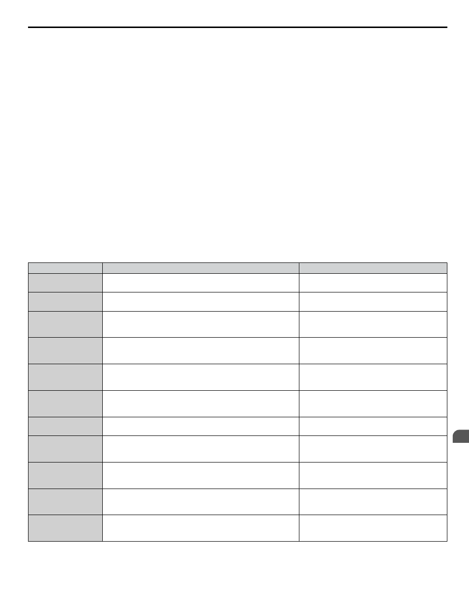
Related Parameters
No.
Parameter Name
Setting Values
H3-01
Terminal A1 Signal Level Selection
Default: 0
Range: 0 to 3
H3-02
Terminal A1 Function Selection
Default: 0
Range: 0 to 32
L5-01
Number of Auto Restart Attempts
Default: 5
Min.: 0
Max.: 10
P1-06
Minimum Pump Speed
Default: 40.0 Hz
Min.: 0.0
Max.: [E1-04]
P4-05
Pre-Charge Loss of Prime Level
Default: 0.0 A
Min.: 0.0
Max.: 1000.0
Q1-01
PID Controller Setpoint 1
Default: 0.0
Min.: 0.0
Max.: 6000.0
Q4-01
Water Level Selection
Default: 0
Range: 0, 1
Q4-02
Water Level Scaling
Default: 100 PSI
Min.: 5
Max.: 500
Q4-03
Water Level Setpoint
Default: 20.0 ft
Min.: 0.0
Max.: 1200.0
Q4-04
Minimum Water Level
Default: 10.0 ft
Min.: 0.0
Max.: 1200.0
Q4-05
Water Level Sleep Delay Time
Default: 5 s
Min.: 0
Max.: 3600
4.5 iQpump Presets and Functions
YASKAWA TOEP YAIP1W 01B YASKAWA AC Drive - iQpump1000 Quick Start Guide
183
4
Start-Up Programming & Operation