Terminals a1, a2, and a3 input signal selection – Yaskawa iQpump1000 AC Drive Quick Start User Manual
Page 149

u
Terminals A1, A2, and A3 Input Signal Selection
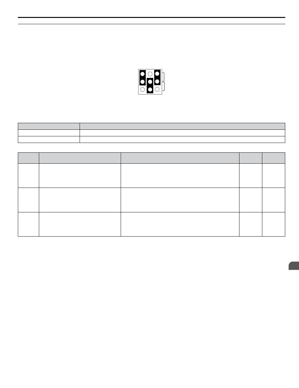
Terminals A1, A2, and A3 can be used to input either a voltage or a current signal. Select the signal type using jumper S1 as
. Set parameters H3-01, H3-05, and H3-09 accordingly as shown in
.
Note:
If terminals A1 and A2 are both set for frequency bias (H3-02 = 0 and H3-10 = 0), both input values will be combined to create the frequency
reference.
V
I
A1 A2 A3
Jumper S1
Figure 3.31 Terminal A2 Set to Current Input; A1 and A3 Set to Voltage Input
Table 3.13 Jumper S1 Settings
Setting
Description
V (top position)
Voltage input (-10 to +10 V or 0 to 10 V)
I (bottom position)
Current input (4 to 20 mA or 0 to 20 mA)
Table 3.14 Voltage/Current Selection Parameter Details
No.
Parameter Name
Description
Setting
Range
Default
Setting
H3-01
Terminal A1 signal level selection
Selects the signal level for terminal A1.
0: 0 to 10 Vdc
1: 0 to 10 Vdc Bipolar
2: 4 to 20 mA
3: 0 to 20 mA
0 to 3
0
H3-05
Terminal A3 signal level selection
Selects the signal level for terminal A3.
0: 0 to 10 Vdc
1: 0 to 10 Vdc Bipolar
2: 4 to 20 mA
3: 0 to 20 mA
0 to 3
0
H3-09
Terminal A2 signal level selection
Selects the signal level for terminal A2.
0: 0 to 10 Vdc
1: 0 to 10 Vdc Bipolar
2: 4 to 20 mA
3: 0 to 20 mA
0 to 3
2
3.8 Control I/O Connections
YASKAWA TOEP YAIP1W 01B YASKAWA AC Drive - iQpump1000 Quick Start Guide
149
3
Electrical Installation