Drive specifications, A.2 drive specifications – Yaskawa iQpump1000 AC Drive Quick Start User Manual
Page 313
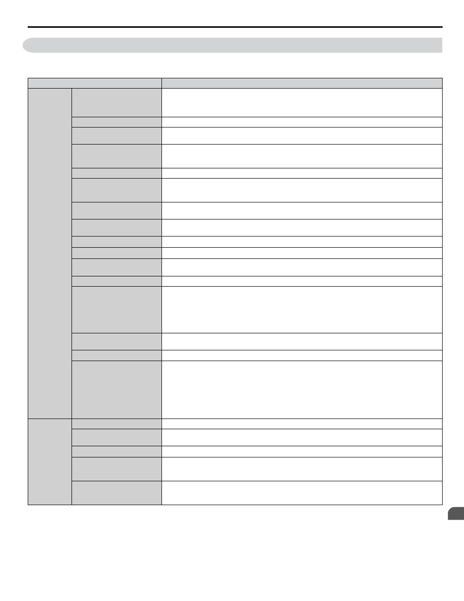
A.2 Drive Specifications
Note:
1. Perform rotational Auto-Tuning to obtain the performance specifications given below.
2. For optimum performance life of the drive, install the drive in an environment that meets the required specifications.
Item
Specification
Control
Character-
istics
Control Method
The following control methods can be set using drive parameters:
• V/f Control (V/f)
• Open Loop Vector Control (OLV)
Frequency Control Range
0.01 to 400 Hz
Frequency Accuracy
(Temperature Fluctuation)
Digital input: within ±0.01% of the max output frequency (-10 to +40 °C)
Analog input: within ±0.1% of the max output frequency (25 °C ±10 °C)
Frequency Setting Resolution
Digital inputs: 0.01 Hz
Analog inputs: 1/2048 of the maximum output frequency setting (11 bit plus sign)
Resolution of analog inputs A1 and A3 is 10 bit + sign in current mode
Output Frequency Resolution 0.001 Hz
Frequency Setting Signal
Main speed frequency reference: DC -10 to +10 V (20 kΩ), DC 0 to +10 V (20 kΩ),
4 to 20 mA (250 Ω), 0 to 20 mA (250 Ω)
Main speed reference: Pulse train input (max. 32 kHz)
Starting Torque
<1>
V/f: 150% at 3 Hz
OLV: 200% at 0.3 Hz
Speed Control Range
<1>
V/f: 1:40
OLV: 1:200
Speed Control Accuracy
<1>
OLV: ±0.2% (25 °C ±10 °C)
Speed Response
<1>
OLV
Torque Limit
Parameters setting allow separate limits in four quadrants
(available in OLV)
Accel/Decel Time
0.0 to 6000.0 s (2 selectable combinations of independent acceleration and deceleration settings)
Braking Torque
Approx. 20% (approx. 125% when using braking resistor)
<2>
• Short-time decel torque
<3>
: over 100% for 0.4/ 0.75 kW motors, over 50% for 1.5 kW motors, and
over 20% for 2.2 kW and above motors
<4>
(overexcitation braking/High Slip Braking: approx. 40%)
• Continuous regenerative torque: approx. 20%
<4>
(approx. 125% with dynamic braking resistor
option
<2>
: 10% ED, 10s)
Braking Transistor
Models 2A0004 to 2A0138, 4A0002 to 4A0072, and 5A0003 to 5A0052 have a built-in braking
transistor.
V/f Characteristics
User-selected programs and V/f preset patterns possible
Main Control Functions
Momentary Power Loss Ride-Thru, Speed Search, Overtorque/Undertorque Detection, Torque Limit,
17 Step Speed (max), Accel/decel Switch, S-curve Accel/decel, 3-wire Sequence, Auto-tuning
(rotational, stationary tuning), Dwell, Cooling Fan on/off Switch, Slip Compensation, Frequency Jump,
Upper/lower Limits for Frequency Reference, DC Injection Braking at Start and Stop, Overexcitation
Braking, High Slip Braking, PID Control (with sleep function), Energy Saving Control, MEMOBUS/
Modbus Comm. (RS-422/RS-485 max, 115.2 kbps), Fault Restart, Application Presets, DriveWorksEZ
(customized function), Removable Terminal Block with Parameter Backup Function, Online Tuning,
KEB, Overexcitation Deceleration, Overvoltage Suppression, Dynamic Noise Control.
Protection
Functions
Motor Protection
Electronic thermal overload relay
Momentary Overcurrent
Protection
Drive stops when output current exceeds 170% of rated output current
Overload Protection
Drive stops when rated output current is 120% for 60 s
<5>
Overvoltage Protection
200 V class: Stops when DC bus voltage exceeds approx. 410 V
400 V class: Stops when DC bus voltage exceeds approx. 820 V
600 V class: Stops when DC bus voltage exceeds approx. 1040 V
Undervoltage Protection
200 V class: Stops when DC bus voltage falls below approx. 190 V
400 V class: Stops when DC bus voltage falls below approx. 380 V
600 V class: Stops when DC bus voltage falls below approx. 475 V
A.2 Drive Specifications
YASKAWA TOEP YAIP1W 01B YASKAWA AC Drive - iQpump1000 Quick Start Guide
313
A
Specifications