Yaskawa iQpump1000 AC Drive Quick Start User Manual
Page 218
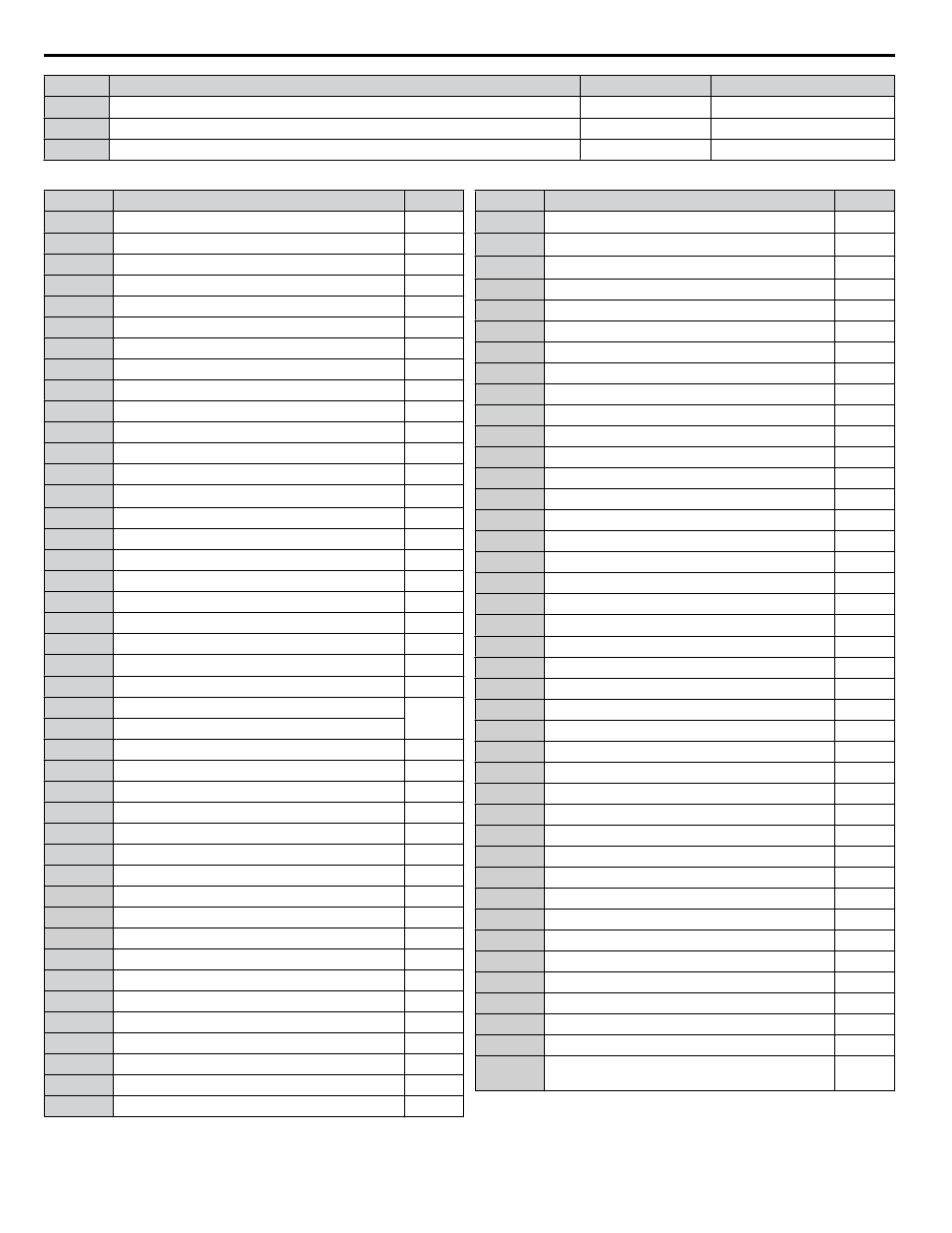
No.
Parameter Name
Setting Range
Default
H2-01
Terminal M1-M2 Function Selection (relay)
0 to 192
37: During Frequency Output
H2-02
Terminal M3-M4 Function Selection (relay)
0 to 192
F: Through Mode
H2-03
Terminal MD-ME-MF Function Selection (relay)
0 to 192
E: Fault
Table 4.21 Multi-Function Digital Output Terminal Settings
Setting
Function
Page
0
During run
–
1
Zero speed
–
2
Speed agree 1
–
3
User-set speed agree 1
–
4
Frequency detection 1
–
5
Frequency detection 2
–
6
Drive ready
–
7
DC bus undervoltage
–
8
During baseblock (N.O.)
–
9
Frequency reference source
–
A
Run command source
–
B
Torque detection 1 (N.O.)
–
C
Frequency reference loss
–
D
<1>
Braking resistor fault
–
E
Fault
–
F
Through mode
–
10
Minor fault
–
11
Fault reset command active
–
12
Timer output
–
13
Speed agree 2
–
14
User-set speed agree 2
–
15
Frequency detection 3
–
16
Frequency detection 4
–
17
Torque detection 1 (N.C.)
–
18
Torque detection 2 (N.O.)
19
Torque detection 2 (N.C.)
–
1A
During reverse
–
1B
During baseblock (N.C.)
–
1E
Restart enabled
–
1F
Motor overload alarm (oL1)
–
20
Drive overheat pre-alarm (oH)
–
22
Mechanical weakening detection
–
2F
Maintenance period
–
30
During torque limit
–
37
During frequency output
–
38
Drive enabled
–
39
Watt hour pulse output
–
3C
LOCAL/REMOTE status
–
3D
During speed search
–
3E
PID feedback low
–
3F
PID feedback high
–
4A
During KEB Ride-Thru
–
4C
During fast stop
–
Setting
Function
Page
4D
oH Pre-alarm time limit
–
4E
<2>
Braking transistor fault (rr)
–
4F
<2>
Braking resistor overheat (oH)
–
50
Waiting to Run
–
51
Sequence timer 1
–
52
Sequence timer 2
–
53
Sequence timer 3
–
54
Sequence timer 4
–
58
Underload detection
–
60
Internal cooling fan alarm
–
71
Secondary PI Feedback Low
–
72
Secondary PI Feedback High
–
80
Pump 2 Control
–
81
Pump 3 Control
–
82
Pump 4 Control
–
83
Pump 5 Control
–
84
Pump 6 Control
–
89
Output 1 Limit
–
8B
Lube Pump or Digital Output Delay
–
8F
Internal Fan On
–
91
Pump Fault
–
92
Transducer Loss
–
93
Setptoint Not Met
–
94
Loss of Prime
–
95
Volute Thermostat Fault
–
96
High Feedback
–
97
Low Feedback
–
98
Low Flow
–
99
Accum Level
–
9A
High Flow
–
9B
Low Water Level
–
9C
Low Suction
–
9D
High Suction
–
A2
Sleep Active
–
A3
Start Delay
–
A4
Pre-Charge
–
A5
Anti-Jam Active
–
A6
De-Scale Active
–
A9
Thrust Mode
–
AA
Utility Start Delay
–
100 to
1AA
Function 0 to AA with inverse output
–
<1> Not available in models 4A0930 and 4A1200.
<2> Not available in models 2A0169 to 2A0415 and 4A0088 to 4A1200.
4.6 Basic iQpump Setup and Application Preset Parameters
218
YASKAWA TOEP YAIP1W 01B YASKAWA AC Drive - iQpump1000 Quick Start Guide