Logic connections, Operational settings – Basler Electric BE1-11m User Manual
Page 100
88
9424200996 Rev L
Protective elements blocked by 60FL should be set so that trip times are 60 milliseconds or greater to
assure proper coordination of blocking.
Block Logic Input
The Block input provides logic-supervision control of the element. In a typical application, the power factor
element will be blocked during motor start-up and until reaching synchronous speed.
When true, the Block input disables the element by forcing the Trip and Pickup outputs to logic 0 and
resetting the element timer. Connect the element Block input to the desired logic in BESTlogicPlus. When
the element is initially selected from the Elements view, the default condition of the Block input is a logic
0.
Logic Connections
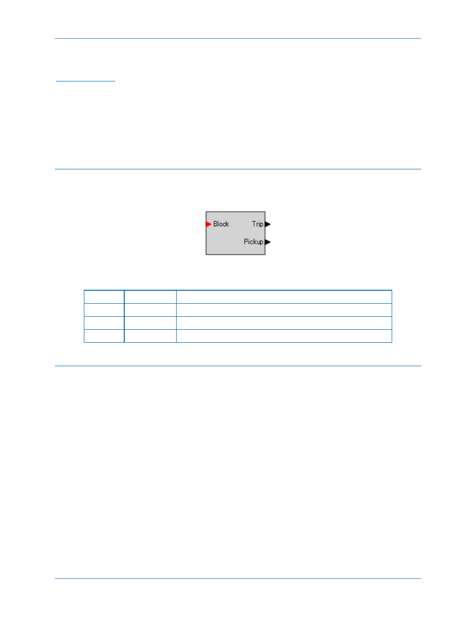
Power factor element logic connections are made on the BESTlogicPlus screen in BESTCOMSPlus. The
power factor element logic block is illustrated in Figure 62. Logic inputs and outputs are summarized in
Table 33.
Figure 62. Power Factor Element Logic Block
Table 33. Logic Inputs and Outputs
Name
Function
Purpose
Block
Input
Disables the 55 function when true
Trip
Output
True when the 55 element is in trip condition
Pickup
Output
True when the 55 element is in pickup condition
Operational Settings
Power factor operational settings are configured on the Power Factor (55) settings screen (Figure 63) in
BESTCOMSPlus. Setting ranges and defaults are summarized in Table 34.
Power Factor (55) Protection
BE1-11m