System parameters - motor configuration – Basler Electric BE1-11m User Manual
Page 555
9424200996 Rev L
543
motor FLA. Enter 60 for the CT ratios on the System Parameters, Sensing Transformers screen shown in
Figure 372. Use Wye CT connections for low burden.
Ground CT Ratios
This large synchronous motor is solidly grounded (to be most effective in power factor management. This
application uses the residual current calculated in the BE1-11m to detect ground faults. No CT ratio must
be entered in this case; leave the default at 1 on the System Parameters, Sensing Transformers screen
shown in Figure 372.
Phase VT Setup
In this example, the phase VT connection is 3-wire, delta. The system voltage is 12 kV. The phase VT
ratio is calculated in Equation 59.
𝑆𝑦𝑠𝑡𝑒𝑚 𝑉𝑜𝑙𝑡𝑎𝑔𝑒
𝑃−𝑃
𝑅𝑒𝑙𝑎𝑦 𝑁𝑜𝑚𝑖𝑛𝑎𝑙 𝑉𝑜𝑙𝑡𝑎𝑔𝑒
𝑃−𝑃
=
12000 𝑉
120 𝑉
= 100
Equation 59. Phase VT Ratio
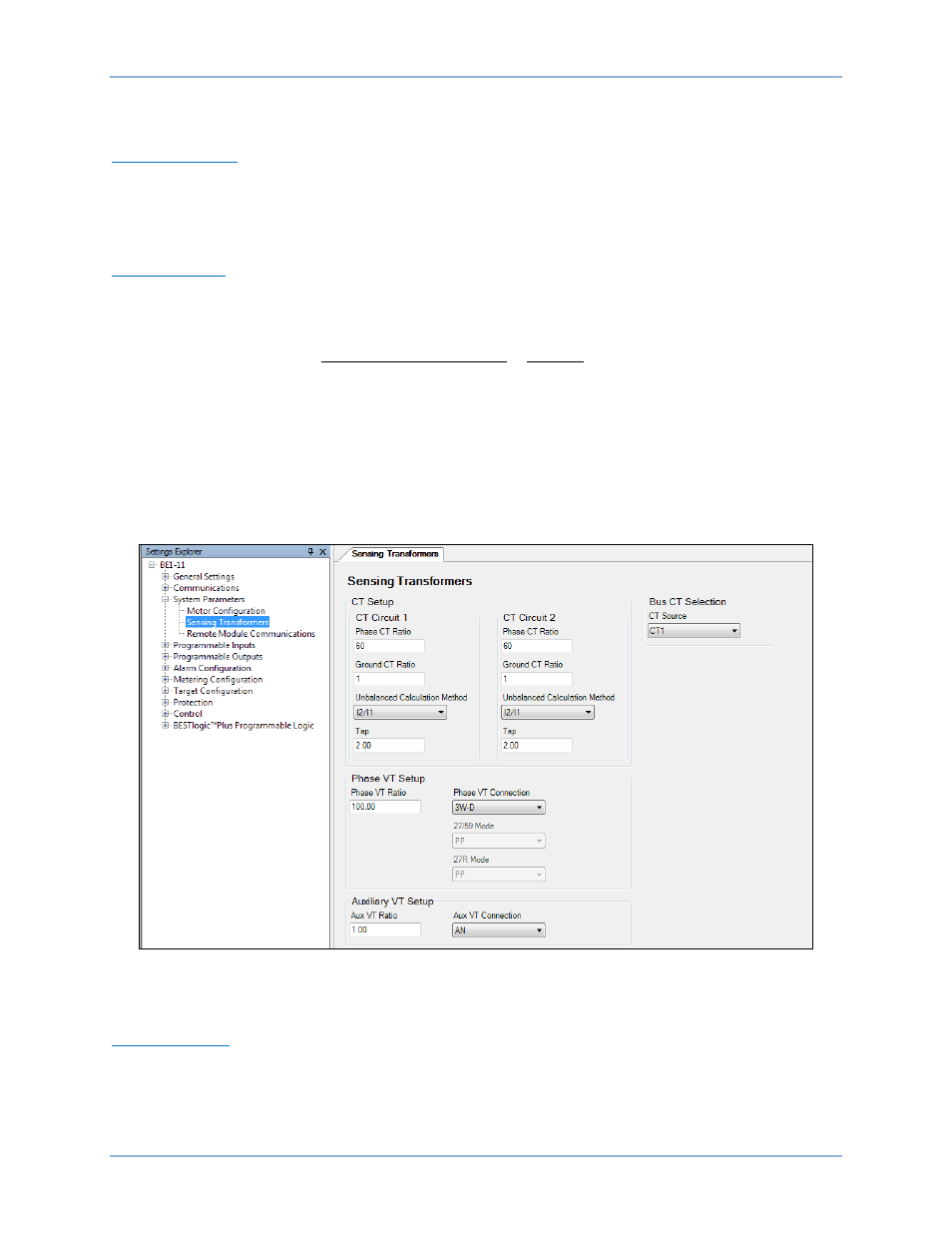
Use the Settings Explorer in BESTCOMSPlus to navigate to the System Parameters, Sensing
Transformers screen shown in Figure 372. Set Phase VT Ratio to 100 and set Phase VT Connection to
3W-D.
The 27 and 59 elements will remain set in primary phase-to-phase quantities, as well as the 27R Mode.
The single-phase input is not used in this application settings example so the Auxiliary VT Setup can
remain unchanged. The Bus CT Selection is the motor incoming power from the bus on CT1 source.
Figure 372. System Parameters, Sensing Transformers Screen
System Parameters - Motor Configuration
Nominal Settings
The system nominal quantities are used for BE1-11m functions such as the 60FL (loss of PT fuse). Enter
all nominal settings in phase-to-neutral quantities and secondary quantities (required by the BE1-11m) on
the System Parameters, Motor Configuration screen shown in Figure 373. The BE1-11m Nominal Settings
must be set for secondary units.
BE1-11m
Settings Calculation Examples