Basler Electric BE1-11m User Manual
Page 199
9424200996 Rev L
187
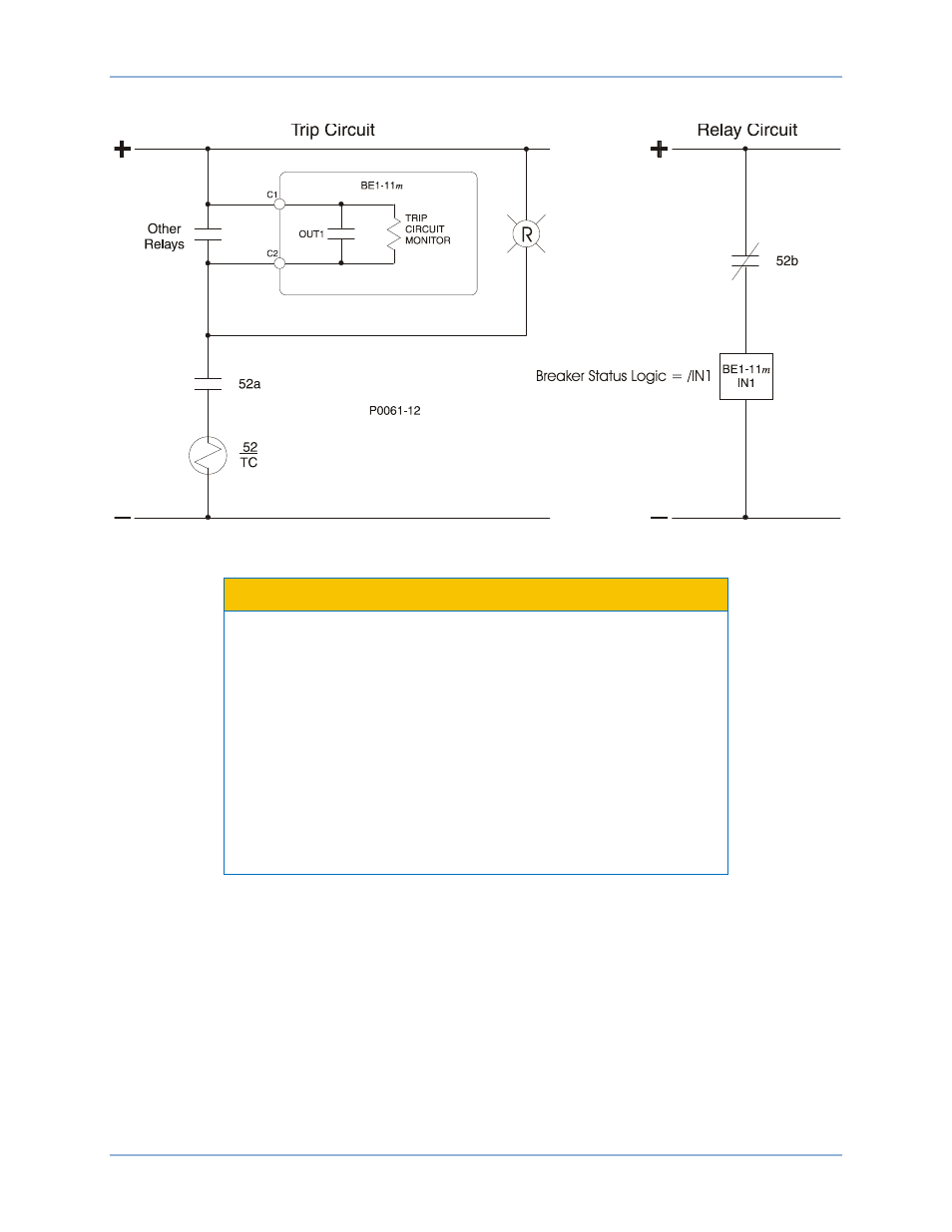
Figure 149 illustrates typical trip circuit monitor connections for the BE1-11m.
Figure 149. Trip Circuit Voltage and Continuity Monitor
Caution
Applications that place other device inputs in parallel with the breaker
trip coil may not perform as desired. The connection of other devices
in parallel with the trip coil causes a voltage divider to occur when the
breaker or trip circuit is open. This may cause false tripping of the
other devices and prevent the BE1-11m trip circuit monitor from
reliably detecting an open circuit. Contact Basler Electric for advice on
this application.
The circuit monitor sensing element has the same rating as the power
supply voltage. If the trip circuit voltage is significantly greater than the
power supply voltage (for example, when using a capacitor trip
device), the user should program the BE1-11m to use one of the other
output relays for tripping. In this situation, the trip circuit monitor
function will not be available.
In Figure 150, a 62X auxiliary relay is shown. In this case, the impedance of the 62X coil is small
compared to the impedance of the TCM circuit so the TCM optical isolator is always on and the TCM is
always at logic 1. This prevents the TCM logic from working even if the trip coil is open. To prevent this
problem, a diode was added as shown in Figure 150 to isolate the TCM circuit from the effects of 62X.
BE1-11m
Trip Circuit Monitor (52TCM)