Time delay verification – Basler Electric BE1-11m User Manual
Page 341
9424200996 Rev L
329
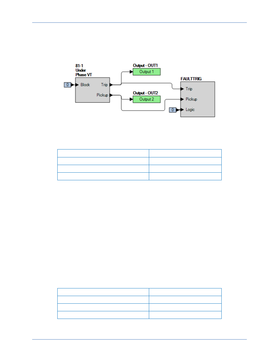
Step 2: Use BESTCOMSPlus to configure the BESTlogicPlus programmable logic shown in Figure 249.
•
Blocking is disabled.
•
OUT1 closes for 81-1 Trip.
•
OUT2 closes for 81-1 Pickup.
•
Fault recording is enabled.
Figure 249. BESTlogicPlus Settings (Underfrequency)
Step 3: Use BESTCOMSPlus to open the Protection, Frequency, Frequency (81-1) screen and send
the first row of test settings in Table 124 to the BE1-11m.
Table 124. Pickup Test Settings (Underfrequency)
Pickup Setting
Time Delay
42 Hz
0 ms
46 Hz
0 ms
48 Hz
0 ms
Step 4: Prepare to monitor the 81-1 function operation. Operation can be verified by monitoring OUT2
Step 5: Connect and apply a 120 Vac, 60-hertz voltage source to terminals C13 (A-phase) and C16
(neutral).
Step 6: Slowly decrease the frequency of the applied voltage until OUT2 closes and record the pickup.
Verify that there is an 81-1-Under target on the front-panel display. Slowly increase the
frequency until OUT2 opens and record the dropout.
Step 7: Repeat step 6 for the 46 Hz and 48 Hz pickup settings listed in Table 124. Record the results.
Step 8: (Optional.) Repeat steps 1 through 7 for settings groups 1, 2, and 3.
Step 9: (Optional.) Repeat steps 1 through 8 for 81-2, 81-3, and 81-4.
Time Delay Verification
Step 1: Use BESTCOMSPlus to open the Protection, Frequency, Frequency (81-1) screen and send
the first row of test settings in Table 125 to the BE1-11m. Commands entered in Table 123
should be retained for this test.
Table 125. Timing Test Settings
Pickup Setting
Time Delay
57.50 Hz
2,000 ms
57.50 Hz
5,000 ms
57.50 Hz
10,000 ms
Step 2: Prepare to monitor the 81-1 timings. Timing accuracy is verified by measuring the elapsed time
between a frequency change and OUT1 closing.
BE1-11m
Frequency (81) Test