Operational settings, Figure 93, N table 52 – Basler Electric BE1-11m User Manual
Page 139
9424200996 Rev L
127
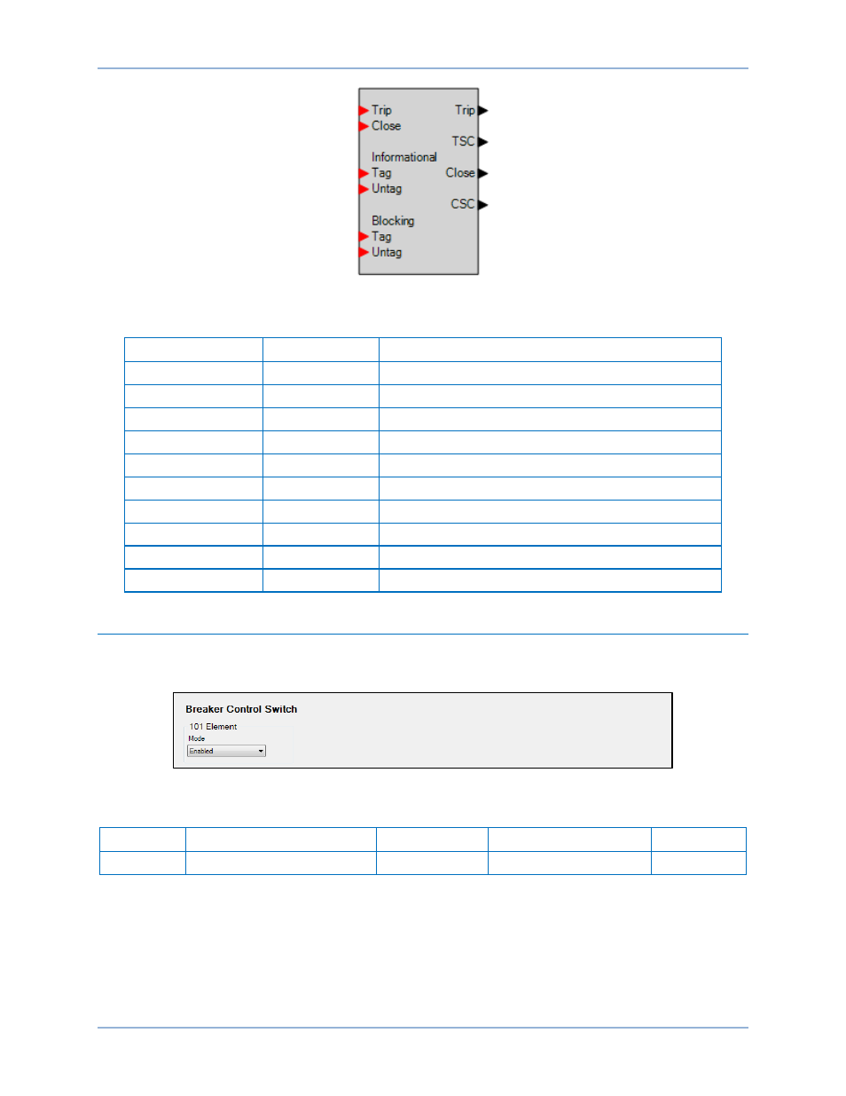
Figure 93. Breaker Control Element Logic Block
Table 52. Logic Inputs and Outputs
Name
Logic Function
Purpose
Trip
Input
Sets the state of the 101 element to Trip
Close
Input
Sets the state of the 101 element to Close
Informational Tag
Input
Sets an informational tag on the 101 element
Informational Untag
Input
Removes the informational tag from the 101 element
Blocking Tag
Input
Sets a blocking tag on the 101 element
Blocking Untag
Input
Removes the blocking tag from the 101 element
Trip
Output
True if the 101 element is in the Trip state
TSC
Output
True after the Trip output momentarily closes
Close
Output
True if the 101 element is in the Close state
CSC
Output
True after the Close output momentarily closes
Operational Settings
Breaker control element operational settings are configured on the Breaker Control Switch (101) settings
screen (Figure 94) in BESTCOMSPlus. Setting ranges and defaults are summarized in Table 53.
Figure 94. Breaker Control Switch Settings Screen
Table 53. Operational Settings
Setting
Range
Increment
Unit of Measure
Default
Mode
Disabled or Enabled
n/a
n/a
Disabled
BE1-11m
Breaker Control Switch (101)