Operational settings, Table 14 – Basler Electric BE1-11m User Manual
Page 64
52
9424200996 Rev L
Table 14. Logic Inputs and Outputs
Name
Logic Function
Purpose
Block
Input
Disables the 81 function when true
Trip
Output
True when the 81 element is in a trip condition
Pickup
Output
True when the 81 element is in a pickup condition
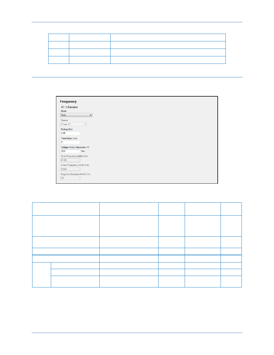
Operational Settings
Frequency element operational settings are configured on the Frequency settings screen (Figure 39) in
BESTCOMSPlus. Setting ranges and defaults are summarized in Table 15.
Figure 39. Frequency Settings Screen
Table 15. Operational Settings
Setting
Range
Increment
Unit of
Measure
Default
Mode
Disabled, Over, Under,
Rate of Change,
Positive Rate of Change,
or Negative Rate of Change
n/a
n/a
Disabled
Pickup
0 or 0.2 to 20 for ROC mode
0 or 15 to 70 for O/U mode
0.01
hertz/sec (ROC)
hertz (O/U)
0
Time Delay
0 to 600,000
varies
milliseconds
0
Voltage Inhibit
0 or 15 to 250
0.1
volts
*
20
81ROC
Over Frequency Inhibit
15 to 70 Hz
0.01
hertz
61
Under Frequency Inhibit
15 to 70 Hz
0.01
hertz
59
Negative Sequence
Inhibit
0 to 99
1
percent
20
* Phase-to-phase and phase-to-neutral settings depend on the Phase VT and Aux VT connection
settings. Refer to the
chapter for more information on these settings.
Frequency (81) Protection
BE1-11m