Time between starts, Figure – Basler Electric BE1-11m User Manual
Page 420
408
9424200996 Rev L
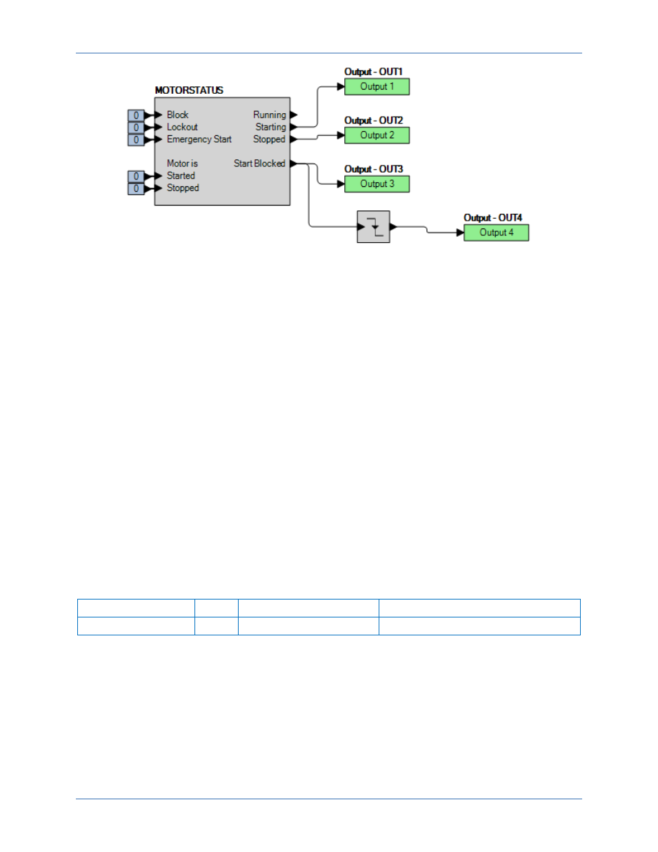
Figure 273. BESTlogicPlus Settings
Step 3: Prepare to monitor restart inhibit function operation. Operation can be verified by monitoring
OUT1 (Starting), OUT2 (Stopped), OUT3 (Start Blocked), and OUT4 (Start Blocked Removed).
Step 4: Connect a three-phase current source to terminals D1 and D2 (IA), D3 and D4 (IB), and D5 and
D6 (IC).
Step 5: Apply 10 Aac three-phase current (simulate motor starting). Verify that OUT1 (Starting) closes
and OUT2 (Stopped) opens.
Step 6: Remove three-phase current. Verify that OUT1 (Starting) opens and OUT2 (Stopped) and
OUT3 (Start Blocked) close. Start the timer when OUT2 (Stopped) closes. The timer will be
stopped when OUT4 (Start Blocked Removed) closes in step 8. The expected timing is 60
seconds.
Step 7: Apply 10 Aac three-phase current and verify that no start is possible when OUT3 (Start
Blocked) is closed during the restart delay of 60 seconds. Remove three-phase current.
Step 8: Stop the timer when OUT4 (Start Blocked Removed) closes and record the time. The expected
timing is 60 seconds. Note that OUT3 (Start Blocked) opens when OUT4 (Start Blocked
Removed) closes.
Step 9: Apply 10 Aac three-phase current (simulate motor starting) and verify that a start is possible.
Remove three-phase current. Allow restart delay timer to expire before proceeding.
Time Between Starts
Step 10: Use BESTCOMSPlus to send the operational settings in Table 180 to the BE1-11m. Reset the
targets.
Table 180. Operational Settings (Time Between Starts)
Setting
Value
BESTCOMSPlus Screen
Description
Time Between Starts
1
Protection, Restart Inhibit
Sets Time Between Starts to 1 minute
Step 11: Use BESTCOMSPlus to configure the BESTlogicPlus Programmable Logic shown in Figure
Step 12: Prepare to monitor the restart inhibit function operation. Operation can be verified by monitoring
OUT1 (Starting), OUT2 (Stopped), OUT3 (Start Blocked), and OUT4 (Start Blocked Removed).
Step 13: Connect a three-phase current source to terminals D1 and D2 (IA), D3 and D4 (IB), and D5 and
D6 (IC).
Step 14: Apply 10 Aac three-phase current (simulate motor starting). Verify that OUT1 (Starting) and
OUT3 (Start Blocked) close and OUT2 (Stopped) opens. Start the timer when OUT3 (Start
Blocked) closes. The timer will be stopped when OUT4 (Start Blocked Removed) closes in step
17. The expected timing is 60 seconds.
Restart Inhibit Test
BE1-11m