Basler Electric BE1-11m User Manual
Page 541
9424200996 Rev L
529
approaching locked-rotor current, and a reduction in terminal voltage depending upon the motor
impedance. The motor can be removed from service faster when using the 50-5 element instead of the
49TC element for jam protection. This results in less heating of the motor allowing it to be returned to
service faster after the cause of the stall has been corrected. The maximum stall time is listed on the
motor nameplate per the NEMA MG-1 standard. In this example, the pickup setting is calculated as 70
percent of LRC as shown in Equation 48. The LRC is found in the motor manufacturer data. Secondary
full load amps is calculated in Equation 38.
𝑃𝑖𝑐𝑘𝑢𝑝 = 70% 𝑜𝑓 𝐿𝑅𝐶 = 0.7 �𝐿𝑅𝐶 ∙ 𝐹𝐿𝐴
𝑆𝑒𝑐𝑜𝑛𝑑𝑎𝑟𝑦
� = 0.7 ∙ 6 ∙ 4.54 = 27.24 𝐴 𝑠𝑒𝑐𝑜𝑛𝑑𝑎𝑟𝑦
Equation 48. 50-5 Pickup
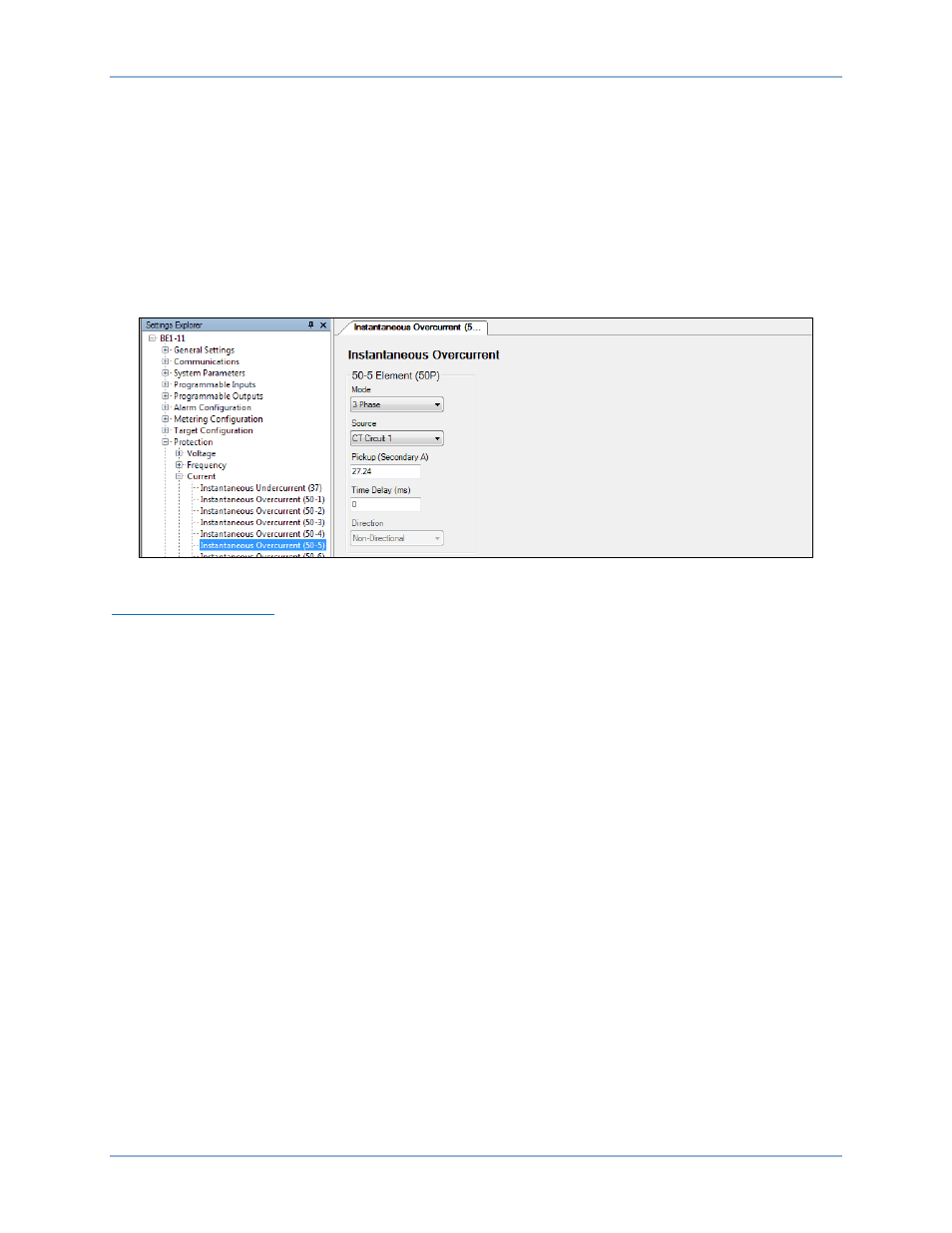
Select three-phase mode and set the Pickup setting to 27.24 A as shown in Figure 356.
Figure 356. Protection, Current, Instantaneous Overcurrent (50-5) Screen
Current Differential (87)
BE1-11m Motor Protection Systems with a style number of xxxxxxxxPxxxxx are equipped with differential
protection. Differential protection is preferred on all motors, but not all motors are built with access to both
ends of the motor windings. In this case, differential protection cannot be used.
Differential protection is selected over other methods because of its sensitivity, speed, and security. The
BE1-11m provides two types of differential protection. The first, flux balance, is used for small motors. The
second type, percent differential, is used when conductor size prevents the use of flux balance CTs (i.e.
motors exceeding 2,500 HP). Flux balance requires one ring or doughnut CT per phase of sufficient
diameter to accommodate conductors from both ends of the motor. When this is not possible, percent
differential mode is used and requires a set of CTs on the terminal side and neutral side of the motor. It is
preferred that both sets of CTs are identical. A motor differential connection example is shown in Figure
357.
Percent differential mode is used in this example. The motor must have all six stator leads brought out so
that CTs can be placed on the input and output leads of each stator winding.
The six CTs have matching characteristics, and for smaller operation currents (during running mode),
Restraint Slope 1 % can be less. However, during the starting mode, CT saturation is large. As a security
measure, choose a large Restraint Slope 2 % to avoid false trips during starting.
Set the Minimum Restrained Pickup to 0.1 for maximum differential sensitivity, which provides optimal
motor protection. This setting is in per units of tap. The minimum pickup current sensitivity is calculated in
Equation 49.
𝑀𝑖𝑛𝑖𝑚𝑢𝑚 𝑃𝑖𝑐𝑘𝑢𝑝 𝐶𝑢𝑟𝑟𝑒𝑛𝑡 𝑆𝑒𝑛𝑠𝑖𝑡𝑖𝑣𝑖𝑡𝑦 = 𝑇𝐴𝑃 ∙ 𝑀𝑖𝑛𝑖𝑚𝑢𝑚 𝑅𝑒𝑠𝑡𝑟𝑎𝑖𝑛𝑒𝑑 𝑃𝑖𝑐𝑘𝑢𝑝 = 2.0 ∙ 0.1 = 0.2 𝐴
Equation 49. Minimum Pickup Current Sensitivity
BE1-11m
Settings Calculation Examples