Logic connections, Operational settings – Basler Electric BE1-11m User Manual
Page 94
82
9424200996 Rev L
Logic Connections
Power element logic connections are made on the BESTlogicPlus screen in BESTCOMSPlus. The power
element logic block is illustrated in Figure 57. Logic inputs and outputs are summarized in Table 29.
Figure 57. Power Element Logic Block
Table 29. Logic Inputs and Outputs
Name
Logic Function
Purpose
Block
Input
Disables the 32 function when true
Trip
Output
True when the 32 element is in a trip condition
Pickup
Output
True when the 32 element is in a pickup condition
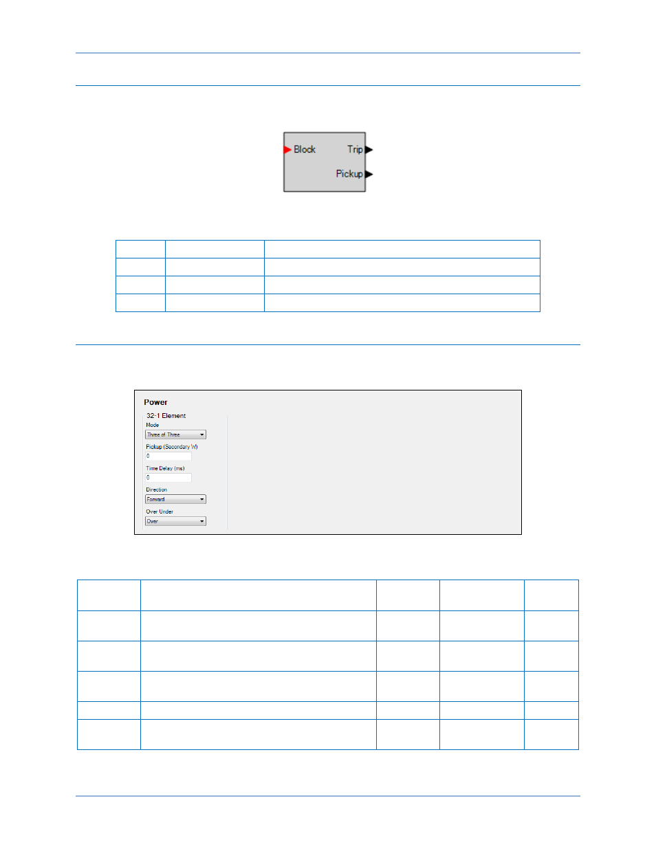
Operational Settings
Power element operational settings are configured on the Power (32) settings screen (Figure 58) in
BESTCOMSPlus. Setting ranges and defaults are summarized in Table 30.
Figure 58. Power Settings Screen
Table 30. Operational Settings
Setting
Range
Increment
Unit of
Measure
Default
Mode
Disabled, One of Three, Two of Three, Three
of Three, or Total Power
n/a
n/a
Disabled
Pickup
0 or 1 to 6,000 (5A CTs)
0 or 1 to 1,200 (1A CTs)
varies
watts
0
Time
Delay
0 or 50 to 600,000
varies
milliseconds
0
Direction
Forward or Reverse
n/a
n/a
Forward
Over
Under
Over or Under
n/a
n/a
Over
Power (32) Protection
BE1-11m