Voting, Element blocking, Logic connections – Basler Electric BE1-11m User Manual
Page 104: Operational settings
92
9424200996 Rev L
annunciate the condition and to initiate corrective action. If a target is enabled for the element, the
BE1-11m will record a target when the Trip output becomes true. See the
chapter for
more information about target reporting.
Voting
The Voting parameter defines the number of RTDs in the group that must exceed the pickup setting to
cause a trip. For example, if the 49RTD-1 Voting setting is three, then at least 3 RTDs in the selected
group must exceed the pickup setting to cause a trip.
Element Blocking
The Block input provides logic-supervision control of the element. When true, the Block input disables the
element by forcing the Trip and Pickup outputs to logic 0 and resetting the element timer. Connect the
element Block input to the desired logic in BESTlogicPlus. When the element is initially selected from the
Elements view, the default condition of the Block input is a logic 0.
Logic Connections
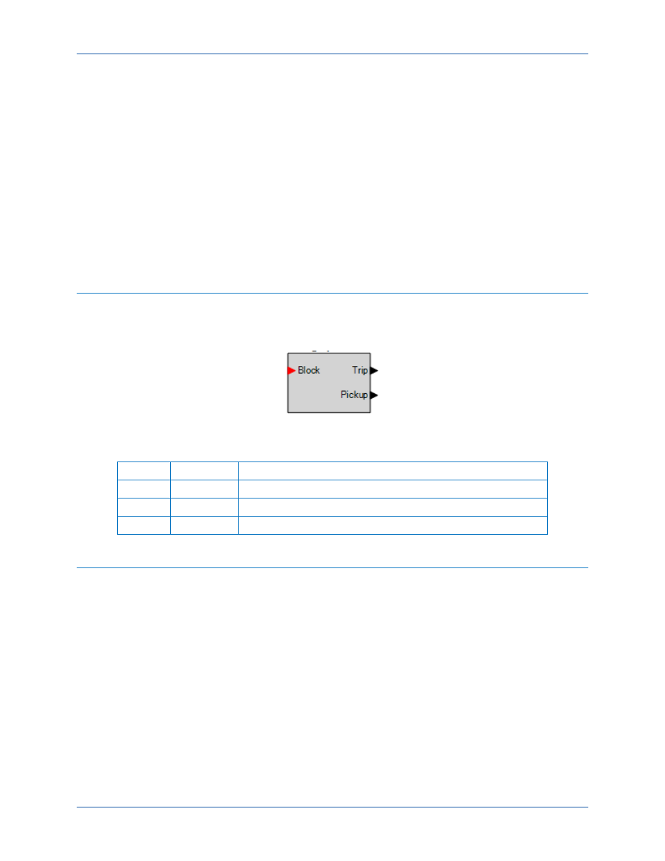
Remote RTD input element logic connections are made on the BESTlogicPlus screen in
BESTCOMSPlus. The remote RTD input element logic block is illustrated in Figure 64. Logic inputs and
outputs are summarized in Table 35.
Figure 64. Remote RTD Input Element Logic Block
Table 35. Logic Inputs and Outputs
Name
Function
Purpose
Block
Input
Disables the 49RTD function when true
Trip
Output
True when the 49RTD element is in trip condition
Pickup
Output
True when the 49RTD element is in pickup condition
Operational Settings
Remote RTD input element operational settings are configured on the Resistance Temperature Detector
settings screen (Figure 65) in BESTCOMSPlus. Setting ranges and defaults are summarized in Table 36.
Resistance Temperature Detector (49RTD) Protection
BE1-11m