Voltage inhibit, Element blocking, Logic connections – Basler Electric BE1-11m User Manual
Page 48
36
9424200996 Rev L
Trip
The Trip output becomes true when an undervoltage pickup condition persists for the duration of the
element Time Delay setting or calculated inverse time. In BESTlogicPlus, the Trip output can be
connected to other logic elements and to a physical relay output to annunciate the condition and to initiate
corrective action. If a target is enabled for the element, the BE1-11m will record a target when the Trip
output becomes true. See the
chapter for more information about target reporting.
Voltage Inhibit
The Voltage Inhibit setting impedes phase undervoltage element operation during undervoltage
conditions that may occur during equipment startup. This setting is expressed in primary or secondary
voltage depending on the Settings Display Mode selected on the General Settings/Display Units settings
screen in BESTCOMSPlus. Its unit of measure depends upon the phase VT connection setting. For four-
wire or phase-to-neutral sensing connections, the inhibit level is expressed in Vpn. For three-wire or
phase-to-phase sensing connections the inhibit level is expressed in Vpp.
Element Blocking
Fuse Loss
The fuse loss (60FL) element of the BE1-11m can be used to block 27P protection when fuse loss or loss
of potential is detected in a three-phase system.
If the 60FL element trip logic is true and Block Phase/V1 is enabled, all functions that use the phase
voltage are blocked. See the
chapter for more information on the 60FL function.
Protective elements blocked by 60FL should be set so that trip times are 60 milliseconds or greater to
assure proper coordination of blocking.
Block Logic Input
The Block input provides logic-supervision control of the element. When true, the Block input disables the
element by forcing the Trip and Pickup outputs to logic 0 and resetting the element timer. Connect the
element Block input to the desired logic in BESTlogicPlus. When the element is initially selected from the
Elements view, the default condition of the Block input is a logic 0.
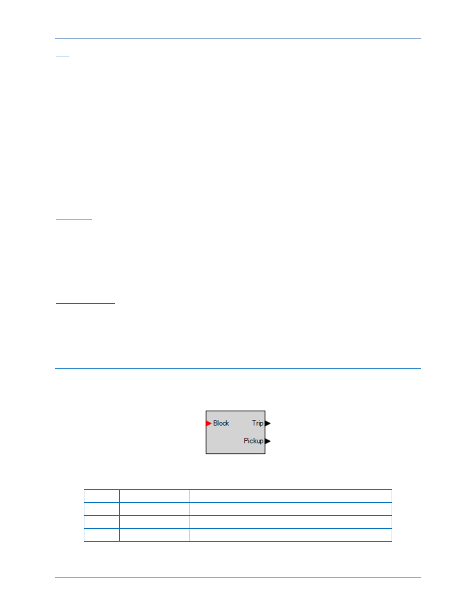
Logic Connections
Phase undervoltage element logic connections are made on the BESTlogicPlus screen in
BESTCOMSPlus. The phase undervoltage element logic block is illustrated in Figure 32. Logic inputs and
outputs are summarized in Table 7.
Figure 32. Phase Undervoltage Element Logic Block
Table 7. Logic Inputs and Outputs
Name
Logic Function
Purpose
Block
Input
Disables the 27P function when true
Trip
Output
True when the 27P element is in a trip condition
Pickup
Output
True when the 27P element is in a pickup condition
Phase Undervoltage (27P) Protection
BE1-11m