Protection - thermal – Basler Electric BE1-11m User Manual
Page 558
546
9424200996 Rev L
Protection - Thermal
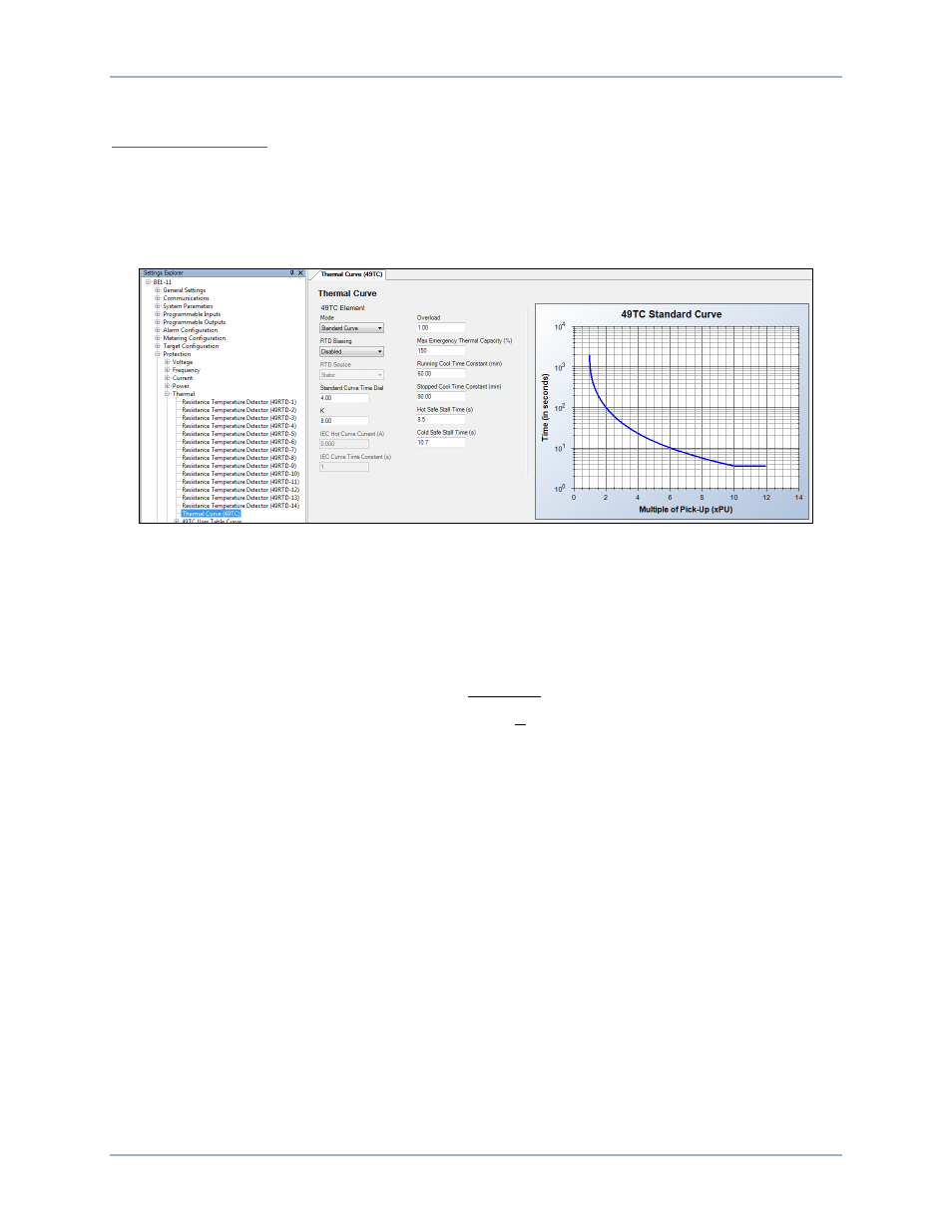
Thermal Curve (49TC)
The 49TC element is the heart of the BE1-11m Motor Protection System. This equivalent current-based
element models the thermal capacity in the motor by using negative-sequence current, reduced voltage
(when custom curves are used), and RTD biasing (when a remote module is used).
Use the Settings Explorer in BESTCOMSPlus to open the Protection, Thermal, Thermal Curve (49TC)
screen and configure the following settings. See Figure 377.
Figure 377. Protection, Thermal, Thermal Curve (49TC) Screen
The settings are explained below.
•
Mode - Standard Curve is used in this example.
•
K - The thermal model operates from equivalent motor current. The K setting determines how much
the negative-sequence current biases the effective current. K is used to determine the equivalent
current as shown in Equation 60. To match NEMA MG-1 standards, use a K factor of 8, unless
otherwise specified.
𝐼
𝑒𝑞
= 𝐼�1 + 𝑘 �
𝐼
2
𝐼
1
�
2
Equation 60. Equivalent Current
where,
I
eq
= equivalent thermal current in PU (unit of thermal pickup current)
I = maximum phase current in PU
I1 = positive-sequence fundamental component of current in PU
I2 = negative-sequence fundamental component of current in PU
K = constant used to determine additional heating due to negative-sequence
current in PU
•
Overload - By default, the thermal model begins timing towards a trip when the effective motor
current exceeds SF (Service Factor)
• FLA (Full Load Amps). The Overload setting adjusts the pickup
level between 90 and 120 percent of SF
• FLA if needed for the motor application; resulting in a total
pickup equation of S
• SF • FLA. In this example, Overload (S) is left at the default setting of 1.00.
•
Standard Curve Time Dial - Examine the motor manufacturer’s data and select a curve time dial to
coordinate closely with the curve shown in Figure 368. Motor thermal limits have three parts based on
three operational conditions: 1) locked rotor or stall, 2) starting or acceleration, and 3) running
overload. The overload protection curve should be set slightly lower than the thermal limits provided
by the manufacturer to ensure that the motor is tripped before reaching the thermal limit. Examine
Figure 378 to determine the standard curve time dial that best coordinates with the motor running
Settings Calculation Examples
BE1-11m