Frequency verification – Basler Electric BE1-11m User Manual
Page 310
298
9424200996 Rev L
Step 3: Connect BE1-11m Terminals C17 (polarity) and C18 to a 180 Hz (third harmonic) ac voltage
source.
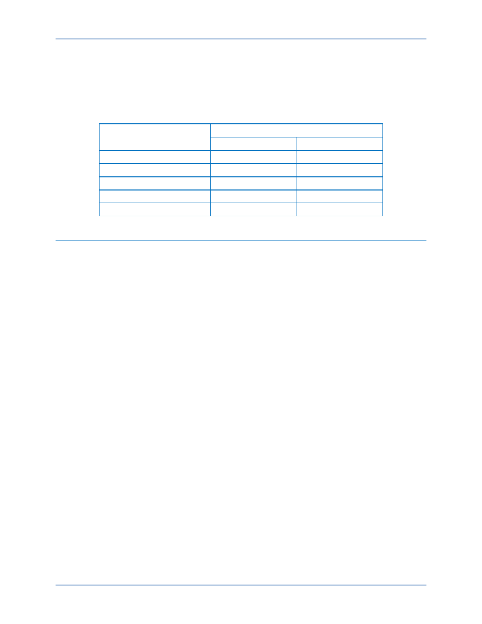
Step 4: Apply the voltage values listed in Table 99 and verify voltage-measuring accuracy by using the
Metering Explorer in BESTCOMSPlus to open the Analog Metering, Voltage, Secondary
Voltage screen. The Metering > Analog Metering > Voltage > Secondary Voltage screen of the
front-panel display can also be monitored to verify voltage measurements. Accuracy is
±0.5%.
Table 99. Aux Voltage Circuit Verification VX & VX 3
rd
Values
Applied Voltage
Measured Voltage
Lower Limit
Upper Limit
30 volts
29.85 V
30.15 V
50 volts
49.75 V
50.25 V
70 volts
69.65 V
70.35 V
90 volts
89.55 V
90.45 V
110 volts
109.45 V
110.55 V
Frequency Verification
Step 1: Connect BE1-11m Terminals C13 (polarity) and C16 (A to Neutral of the three-phase voltage
input) to a 60 hertz ac voltage source (line voltage).
Step 2: Connect BE1-11m Terminals C17 (polarity) and C18 (Auxiliary Voltage Input) to a second 60-
hertz ac voltage source (bus voltage).
Step 3: Apply 115 volts at 0 degrees and 60 hertz to both sources. Verify the measuring accuracy of the
line and bus frequency by using the Metering Explorer in BESTCOMSPlus to open the Analog
Metering, Frequency screen. The Metering > Analog Metering > Frequency screen of the front-
panel display can also be monitored to verify frequency measurements.
Acceptance Testing
BE1-11m