Logic timers (62), Element operation, Mode – Basler Electric BE1-11m User Manual
Page 129
9424200996 Rev L
117
Logic Timers (62)
Eight logic timer (62) elements emulate virtually any type of timer used in power system applications.
The eight, identical logic timer elements are designated 62-1, 62-2, 62-3, 62-4, 62-5, 62-6, 62-7, and 62-
8. Element logic connections are made on the BESTlogic
™Plus screen in BESTCOMSPlus® and element
operational settings are configured on the Logic Timers (62) settings screen in BESTCOMSPlus. A
summary of the logic inputs and outputs and operational settings appears at the end of this chapter.
BESTCOMSPlus Navigation Path: Settings Explorer, Control, Logic Timers (62)
HMI Navigation Path: Settings Explorer, Control, Timer Setup 62, Settings Group x (x = 0 to 3)
Element Operation
Each timer has two time delay settings. The duration of the timers is established by the Time Delay 1 (T1)
setting and the Time Delay 2 (T2) setting. Assertion of the Initiate input starts the timing sequence.
The functioning of the output is dependent upon the type of timer as specified by the mode setting. In
BESTlogicPlus, the output can be connected to other logic elements or a physical relay output to alert the
operator of a condition. If a target is enabled for the element, the BE1-11m will record a target when the
output becomes true. See the
chapter for more information about target reporting.
Mode
Six operating modes are available: Pickup/Dropout, One-Shot/Non-Retriggerable, One-
Shot/Retriggerable, Oscillator, Integrating Timer, and Latched.
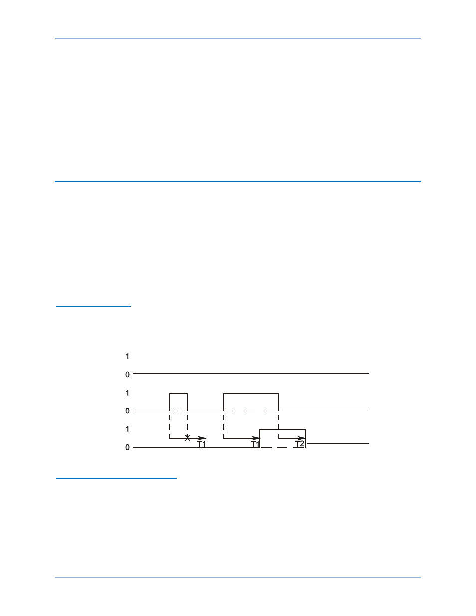
Pickup/Dropout Mode
The output changes to logic true if the Initiate input is true for the Duration of Pickup Time Delay (T1). See
Figure 80. If the Initiate input toggles to false before time T1, the T1 timer is reset. Once the output of the
timer toggles to true, the Initiate input must be false for the Duration of Dropout Time Delay (T2). If the
Initiate input toggles to true before time T2, the output stays true and the T2 timer is reset.
Figure 80. Pickup/Dropout Mode
One-Shot/Non-Retriggerable Mode
The one-shot nonretriggerable timer starts its timing sequence when the Initiate input changes from false
to true. See Figure 81. The timer will time for Delay Time (T1) and then the output will toggle to true for
Duration Time (T2). Additional initiate input changes of state are ignored until the timing sequence is
completed. If the T2 timer is set to 0, this timer will not function. The timer will return to false if the Block
input becomes true.
P
0
0
3
5
-3
0
0
2
-2
7
-0
6
62-x
Block
Initiate
BE1-11m
Logic Timers (62)