Direction of power flow – Basler Electric BE1-11m User Manual
Page 92
80
9424200996 Rev L
Direction of Power Flow
In addition to exceeding the power pickup threshold, direction of power flow (forward or reverse) must
match the directional setting for the 32 element to operate. In the BE1-11m, the forward and reverse
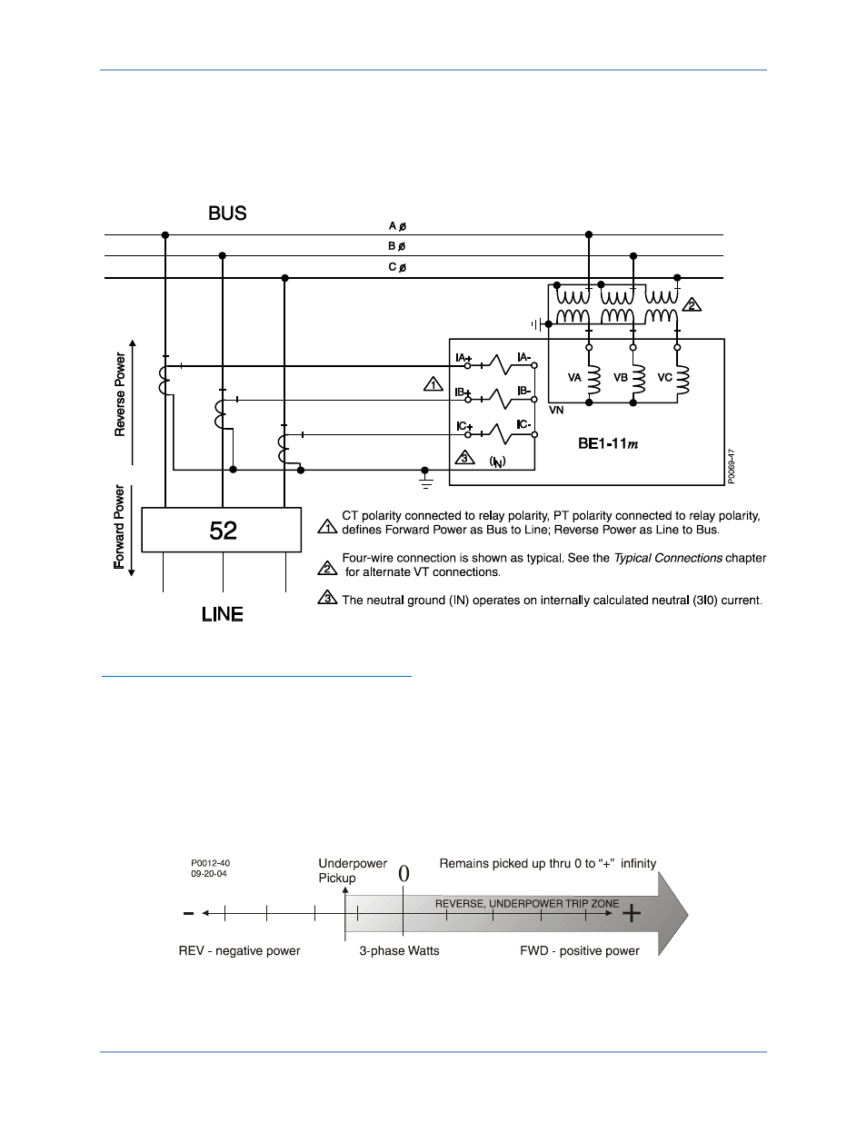
directions are defined by the polarity voltage and current connections to the BE1-11m as shown in Figure
55. Based on IEEE polarity convention, forward power is defined as bus to line and reverse power is
defined as line to bus.
Figure 55. Direction of Power Flow Defined by the Polarity of Voltage and Current Connections
Establishing Forward and Reverse Pickup Values
Three-phase power pickup settings for the power elements are always positive regardless of the
directional setting. However, it is useful in understanding the element response to visualize the forward
direction as positive power and the reverse direction as negative power. If we think in terms of a forward
and reverse scale with zero (0) in the middle as shown in Figure 56, positive and negative power flows
relative to the forward and reverse directional setting. For example, assume an intertie application where
the Area EPS (electric utility) requires the Local EPS (source of non-utility generation) to separate from
the Area EPS (trip the intertie breaker) if any power flows towards the Area EPS. For illustrative purposes,
assume that the BUS in Figure 55 is the Local EPS, 52 is the intertie breaker, and LINE is the Area EPS.
Normal power flow is from the Area EPS to the Local EPS, which happens to be an industrial facility with
local generation used for peak shaving.
Figure 56. Forward and Reverse Pickup Values
Power (32) Protection
BE1-11m