Phase vt setup, Auxiliary vt setup, Bus ct selection – Basler Electric BE1-11m User Manual
Page 299: Settings

9424200996 Rev L
287
Tap
This setting adjusts the measured currents to eliminate magnitude mismatch prior to being used by the
optional 87 differential function.
Phase VT Setup
The BE1-11m requires setting information about the VT ratio, the phase connections, and the operating
modes for the 27/59 and 27R functions. These settings are used by the metering and fault reporting
functions to display measured quantities in primary units. The voltage input circuit settings also determine
which power measurement calculations are used. Most of these connections such as 3W-D, 4W-Y, AN, or
AB are self-explanatory.
Auxiliary VT Setup
The auxiliary voltage input (Vx) connection can be set for AB, BC, CA, AN, BN, CN, or Ground. The Vx
input connection is set to Ground when connected to a source of ground unbalance voltage or residual
voltage such as a generator grounding resistor, broken delta VT connection, or capacitor bank star point.
Bus CT Selection
The CT Source setting selects the set of CTs to use in calculations for power protection (32, 40Q) on
protection systems equipped with two sets of CTs.
Settings
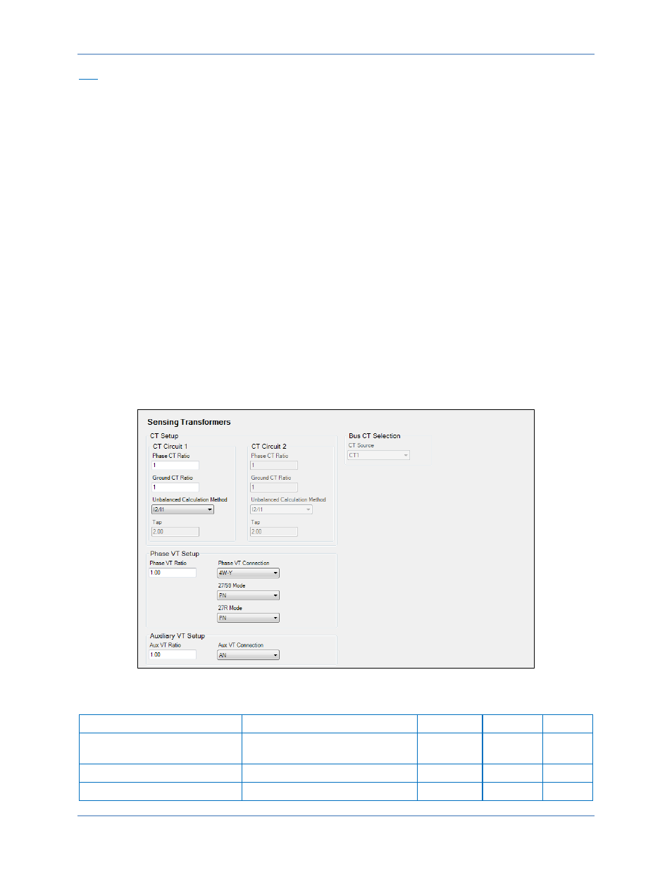
Sensing transformers settings are configured on the Sensing Transformers settings screen (Figure 239)
in BESTCOMSPlus. Setting ranges and defaults are summarized in Table 94.
Figure 239. Sensing Transformers Settings Screen
Table 94. Sensing Transformers Settings
Setting
Range
Increment
Unit
Default
Phase/Ground CT Ratio
1 to 50,000
0.01
turns
ratio
1
Unbalanced Calculation Mode
I2/I1 or Average
n/a
n/a
I1/I2
Tap
BE1-11m
Configuration