Logic connections, Operational settings – Basler Electric BE1-11m User Manual
Page 132
120
9424200996 Rev L
Block input to the desired logic in BESTlogicPlus. When the element is initially selected from the
Elements view, the default condition of the Block input is a logic 0.
Logic Connections
Logic timer element logic connections are made on the BESTlogicPlus screen in BESTCOMSPlus. The
logic timer element logic block is illustrated in Figure 86. Logic inputs and outputs are summarized in
Table 48.
Figure 86. Logic Timer Element Logic Block
Table 48. Logic Inputs and Outputs
Name
Logic Function
Purpose
Initiate
Input
Starts the 62 timing sequence
Block
Input
Disables the 62 function when true
Output
Output
True when 62 timing criteria have been met according to mode
Operational Settings
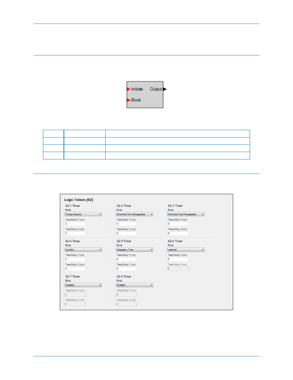
Logic timer element operational settings are configured on the Logic Timers (62) settings screen (Figure
87) in BESTCOMSPlus. Setting ranges and defaults are summarized in Table 49.
Figure 87. Logic Timers Settings Screen
Logic Timers (62)
BE1-11m