Remote rtd, Module – Basler Electric BE1-11m User Manual
Page 568
556
9424200996 Rev L
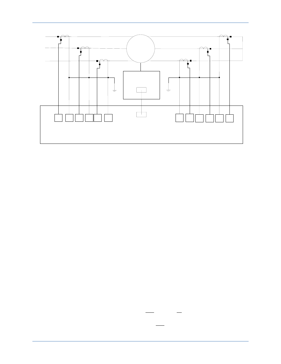
Figure 391. Motor Differential Connection Example
This example uses percent differential mode. The motor must have all six stator leads brought out so that
CTs can be placed on the input and output leads of each stator winding.
The six CTs have matching characteristics, and for smaller operation currents (during running mode),
Restraint Slope 1 % can be less. However, during the starting mode, CT saturation is large. As a security
measure, choose a large Restraint Slope 2 % to avoid false trips during starting.
Set the Minimum Restrained Pickup to 0.1 for maximum differential sensitivity, which provides optimal
motor protection. This setting is in per units of tap. The minimum pickup current sensitivity is calculated in
Equation 72.
𝑀𝑖𝑛𝑖𝑚𝑢𝑚 𝑃𝑖𝑐𝑘𝑢𝑝 𝐶𝑢𝑟𝑟𝑒𝑛𝑡 𝑆𝑒𝑛𝑠𝑖𝑡𝑖𝑣𝑖𝑡𝑦 = 𝑇𝐴𝑃 ∙ 𝑀𝑖𝑛𝑖𝑚𝑢𝑚 𝑅𝑒𝑠𝑡𝑟𝑎𝑖𝑛𝑒𝑑 𝑃𝑖𝑐𝑘𝑢𝑝 = 2.0 ∙ 0.1 = 0.2 𝐴
Equation 72. Minimum Pickup Current Sensitivity
CT Circuit 1 Tap and CT Circuit 2 Tap are shown here, but calculated from the System Parameters,
Sensing Transformers screen (Figure 372). With equal CT ratios, the secondary currents through the
BE1-11m restraint algorithm for external faults and load are similar, and the operating current is very
small. If the differential CTs do not match, use the TAP settings on the System Parameters, Sensing
Transformers screen to balance the differential.
Running Slope
In running mode, the differential can be more sensitive, yet provide security and reliability at 15 percent as
described by IEEE C37.96-2000, IEEE Guide for AC Motor Protection. Set the Restraint Slope 1 %
setting to 15.
Starting Slope
The BE1-11m considers the motor to be starting when current is greater than 2
• FLA in any phase. The
starting mode ends when current in all three phases drops below 2
• FLA. Therefore, the 2
nd
Slope Pickup
(starting) should be set at the point that restraint current is 2
• FLA where motor torques and heating
settle quickly to running mode currents (as observed in typical time-current curves). See Equation 73.
2𝑛𝑑 𝑆𝑙𝑜𝑝𝑒 𝑃𝑖𝑐𝑘𝑢𝑝 𝐶𝑢𝑟𝑟𝑒𝑛𝑡 = 𝐹𝐿𝐴 ∙
1
𝐶𝑇𝑅
∙ 2 = 205 ∙
1
60
∙ 2 = 6.83 𝐴
2𝑛𝑑 𝑆𝑙𝑜𝑝𝑒 𝑃𝑖𝑐𝑘𝑢𝑝 𝑆𝑒𝑡𝑡𝑖𝑛𝑔 =
6.83
2.0 = 3.42 𝐴
M
A
1
I
A
1
•
A
2
I
A
1
A
3
I
B
1
•
A
4
I
B
1
A
5
I
C
1
•
A
6
I
C
1
B
5
I
C
1
•
B
6
I
C
1
B
1
I
A
2
•
B
2
I
A
2
B
3
I
B
2
•
B
4
I
B
2
Remote RTD
Module
BE
1
-
11
m
/
6
Stator RTDs
/
2
Bearing RTDs
/
1
Ambient RTDs
RJ
-
45
RJ
-
45
A
B
C
Settings Calculation Examples
BE1-11m