Pickup verification (3i0 mode) – Basler Electric BE1-11m User Manual
Page 353
9424200996 Rev L
341
Table 133. Timing Test Settings (Phase Mode)
Pickup Setting
Time Delay
0.5 A
2,000 ms
0.5 A
5,000 ms
0.5 A
10,000 ms
Step 3: Connect and apply 0.45 A to BE1-11m terminals D1 and D2 (A-phase).
Step 4: Step the A-phase current up to 0.75 A. Measure the time delay and record the result.
Step 5: Repeat step 4 for the 5,000 ms and 10,000 ms time delay settings of Table 133. Record the
results.
Step 6: (Optional.) Repeat steps 1 through 5 for the B-phase and C-phase current inputs.
Step 7: (Optional.) Repeat steps 1 through 6 for settings group 1, 2, and 3.
Step 8: (Optional.) Repeat steps 1 through 7 for 50-2, 50-3, 50-4, 50-5, and 50-6.
Step 9: (Optional.) Repeat steps 1 through 8 with CT Circuit 2 as the source for protection systems
equipped with two sets of CTs. In step 3, replace D1 with F1, D2 with F2, etc.
Pickup Verification (3I0 Mode)
Step 1: Use BESTCOMSPlus to send the operational settings in Table 134 to the BE1-11m. Reset all
targets.
Table 134. Operational Settings (3I0 Mode)
Setting
Value
BESTCOMSPlus Screen
Description
Phase CT
Ratio
1
System Parameters, Sensing
Transformers
Sets phase CT ratio to 1
Element
Mode
3I0
Protection, Current,
Instantaneous Overcurrent (50-1)
Enables 50-1 function for 3I0 mode
Source
CT Circuit 1
Protection, Current,
Instantaneous Overcurrent (50-1)
Selects CT circuit 1 as the source
50-1
Residual
Enabled
Target Configuration, Targets
Enables residual target for 50-1
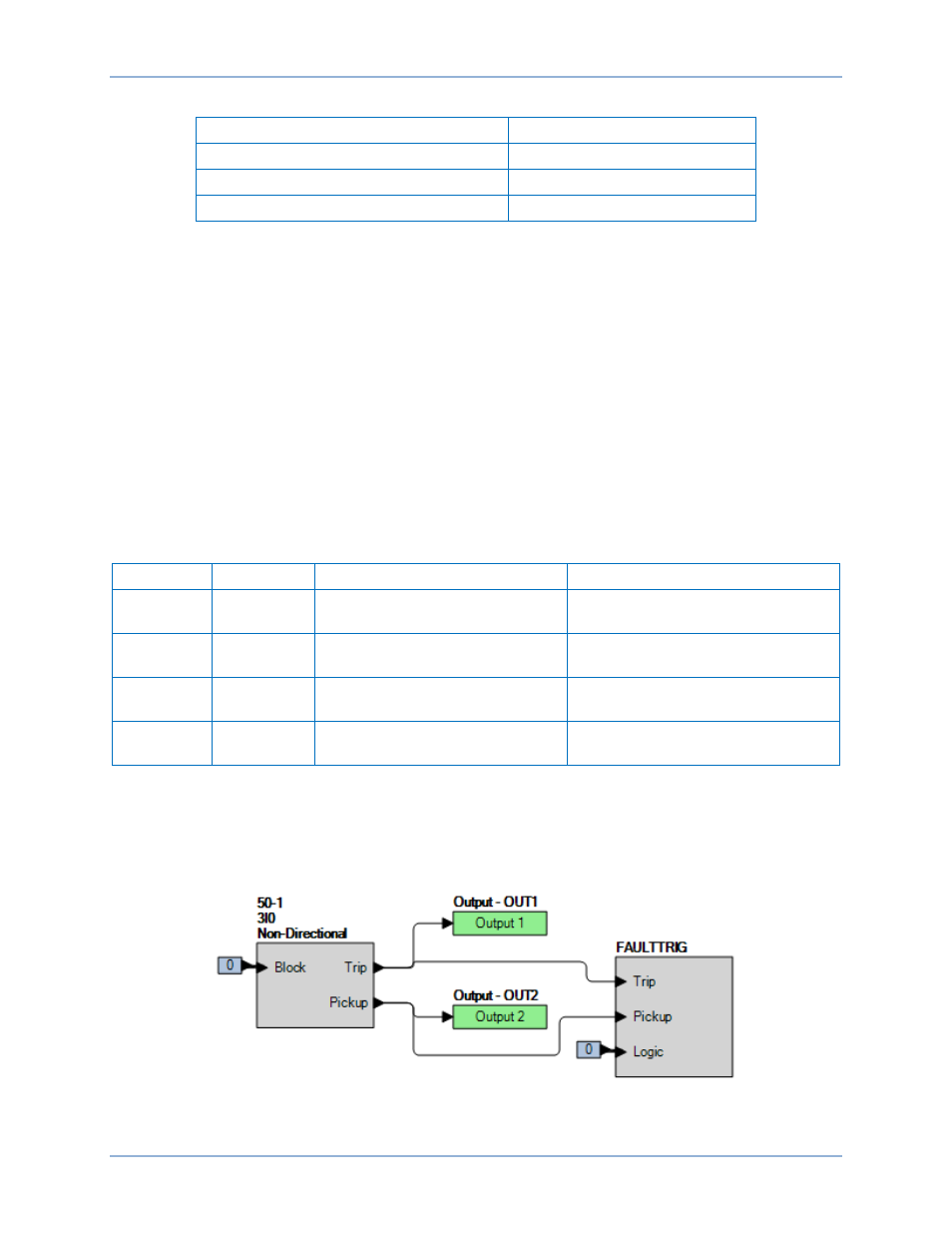
Step 2: Use BESTCOMSPlus to configure the BESTlogicPlus programmable logic shown in Figure 254.
•
Blocking is disabled.
•
OUT1 closes for 50-1 Trip.
•
OUT2 closes for 50-1 Pickup.
•
Fault recording is enabled.
Figure 254. BESTlogicPlus Settings (3I0 Mode)
BE1-11m
Instantaneous Overcurrent (50) Test