Clearing the on-screen logic diagram, Bestlogic™plus examples, Example 1 - or gate connections – Basler Electric BE1-11m User Manual
Page 267: Example 2 - inverse overcurrent logic diagram, Bestlogic ™plus examples
9424200996 Rev L
255
You can skip the print preview and go directly to print by clicking on the Printer icon on the BESTlogicPlus
Programmable Logic toolbar. A dialog box, Select Views to Print opens allowing you to check which views
you would like to print. Next, the Print dialog box opens with the typical Windows choice to setup the
properties of printer. Execute this command, as necessary, and then select Print.
A Page Setup icon is also provided on the BESTlogicPlus Programmable Logic toolbar allowing you to
select Paper Size, Paper Source, Orientation, and Margins.
Clearing the On-Screen Logic Diagram
Click the Clear button to clear the on-screen logic diagram on all logic pages and start over.
BESTlogic
™Plus Examples
Example 1 - OR Gate Connections
Figure 209 illustrates a typical OR gate connection. In this example, OUT5 will become active when either
the Major Alarm OR the Minor Alarm OR both is true.
Figure 209. Example 1 - OR Gate Connections
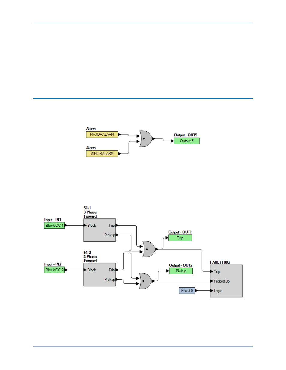
Example 2 - Inverse Overcurrent Logic Diagram
Figure 210 illustrates a typical logic diagram of two inverse overcurrent elements set up to trip outputs
and trigger fault reports. The 51-1 function is blocked when IN1 is true. The 51-1 function is blocked when
IN2 is true. OUT1 is true when either the 51-1 or 51-2 is in a trip condition. OUT2 is true when either the
51-1 or 51-2 is in a pickup condition. The fault trigger logic block ensures that faults are recorded.
Figure 210. Example 2 - Inverse Overcurrent Logic Diagram
BE1-11m
BESTlogic
™Plus