Synchronous motor settings calculation example – Basler Electric BE1-11m User Manual
Page 549
9424200996 Rev L
537
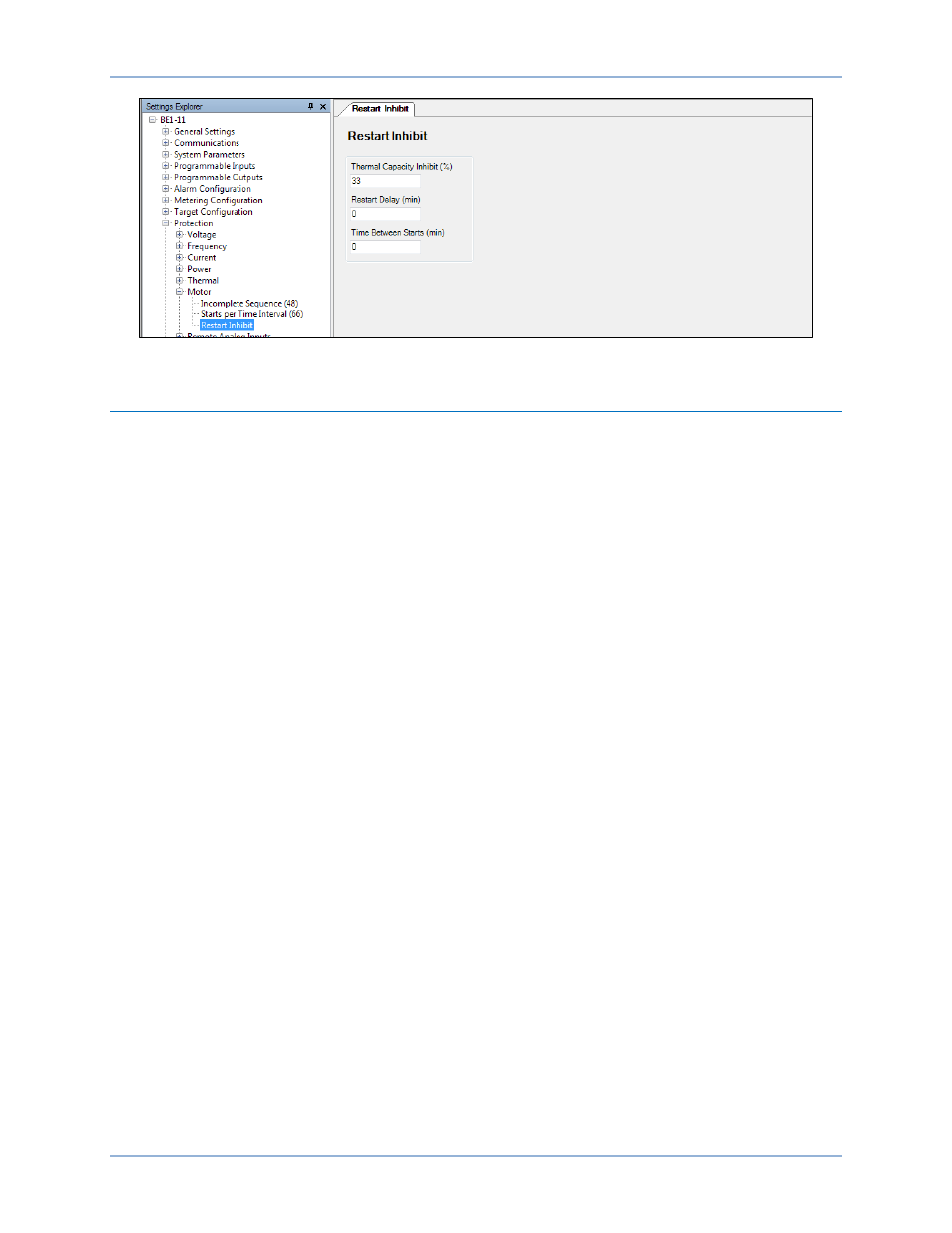
Figure 366. Protection, Restart Inhibit Screen
Synchronous Motor Settings Calculation Example
This logic and settings scheme is for a particular synchronous motor application. You can adapt this
scheme by changing the function block operation and settings. The logic in this scheme differs from the
default induction motor scheme. There are different motor parameters, addition of the Power Factor (55)
element, a detailed example of using User Programmable Alarms, and an example of using the analog
output on the remote RTD module. The synchronous motor requires an excitation system that supplies
field at the correct moment after the motor is started as an induction motor. This example shows one
method to accomplish this task; the Running logic output switches online the excitation circuits via relay
output 6 (OUT6) to achieve synchronous speed. See Figure 407. Other methods are available.
This example uses a 5,000-HP, 12-kV motor with six leads (stator neutrals brought out for differential
protection). The scheme includes thermal model protection (49TC), as well as RTD (Resistance
Temperature Detector) backup. The motor is solidly grounded. A single-line drawing is shown in Figure
367.
BE1-11m
Settings Calculation Examples