Basler Electric BE1-11m User Manual
Page 567
9424200996 Rev L
555
The motor can be removed from service faster when using the 50-6 element instead of the 49TC element
for jam protection. This fast tripping for a jammed condition results in less motor heating, allowing the
motor to be returned to service faster after the cause of the stall (jam) has been corrected.
The maximum stall time is listed on the motor name plate per the NEMA MG-1 standard. In this example,
the conservative protection pickup setting is calculated as 70 percent of LRA as shown in Equation 71.
𝑃𝑖𝑐𝑘𝑢𝑝 = 70% 𝑜𝑓 (𝐿𝑅𝐴) ∙
1
𝐶𝑇𝑅
= 0.7 ∙ (755 𝐴) ∙
1
60
= 8.808 𝐴 𝑠𝑒𝑐𝑜𝑛𝑑𝑎𝑟𝑦
Equation 71. 50-6 Pickup
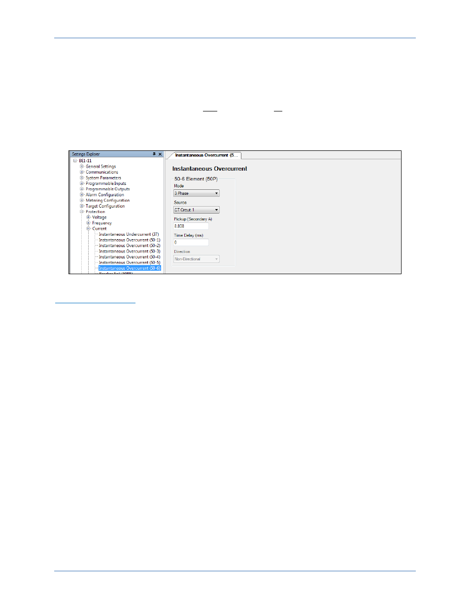
Select three-phase mode and set the Pickup setting to 8.808 as shown in Figure 390.
Figure 390. Protection, Current, Instantaneous Overcurrent (50-6) Screen
Current Differential (87)
BE1-11m Motor Protection Systems with a style number of xxxxxxxxPxxxxx are equipped with differential
protection. Differential protection is preferred on all motors, but not all motors are built with access to both
ends of the motor windings. In this case, differential protection cannot be used.
Differential protection is selected over other methods because of its sensitivity, speed, and security. The
BE1-11m provides two types of differential protection. One method, flux balance, is used for small motors.
Flux balance requires one ring or doughnut CT per phase of sufficient diameter to accommodate
conductors from both ends of the motor. When this is not possible, another method, percent differential is
used when conductor size prevents the use of flux balance CTs (i.e. motors exceeding 2,500 HP).
Percent differential mode requires a set of CTs on the terminal side and neutral side of the motor. It is
preferred that both sets of CTs are identical. A motor differential connection example is shown in
Figure 391.
BE1-11m
Settings Calculation Examples