Inhibit functions, Element blocking, Logic connections – Basler Electric BE1-11m User Manual
Page 63
9424200996 Rev L
51
•
Faults exceeding the pickup setting by 0.57 Hz/s are detected in 2 cycles
•
Faults exceeding the pickup setting by 0.24 Hz/s are detected in 4 cycles
•
Faults exceeding the pickup setting by 0.08 Hz/s are detected in 8 cycles
•
No pickup detection time will be greater than 16 cycles
In BESTlogicPlus, the Pickup output can be connected to other logic elements to annunciate the condition
or control other elements in logic.
Assertion of the Pickup output initiates a timer which begins timing toward a trip. The duration of the timer
is established by the Time Delay setting. A Time Delay setting of zero (0) makes the 81 element
instantaneous (with the exception of the pickup detection time).
If an ROC pickup condition persists for the duration of the element Time Delay setting, the element Trip
output becomes true. In BESTlogicPlus, the Trip output can be connected to other logic elements or a
physical relay output to annunciate the condition and initiate corrective action. If a target is enabled for the
element, the BE1-11m will record a target when the Trip output becomes true. See the
chapter for more information about target reporting.
If the pickup condition subsides before the element time delay expires, the timer and Pickup output are
reset, no corrective action is taken, and the element is rearmed for any other occurrences of a frequency
ROC fault.
Inhibit Functions
Frequency ROC protection can be inhibited by the degree of underfrequency or overfrequency or the
percentage of negative sequence voltage.
The Overfrequency Inhibit setting disables frequency ROC protection when the sensed frequency
exceeds the setting threshold. Likewise, the Underfrequency Inhibit setting disables frequency ROC
protection when the sensed frequency decreases below the setting threshold.
Frequency ROC protection can be inhibited when the percentage of negative sequence voltage exceeds
the limit established by the Negative Sequence Inhibit setting. A Negative Sequence Inhibit setting of zero
(0) inhibits this feature.
Element Blocking
This input allows for logic supervision or control of the element.
Each frequency protection element has a Block logic input which when true, disables an element by
forcing the Trip and Pickup outputs to logic 0 and resetting the element timer. An element Block input is
connected to the desired logic in BESTlogicPlus.
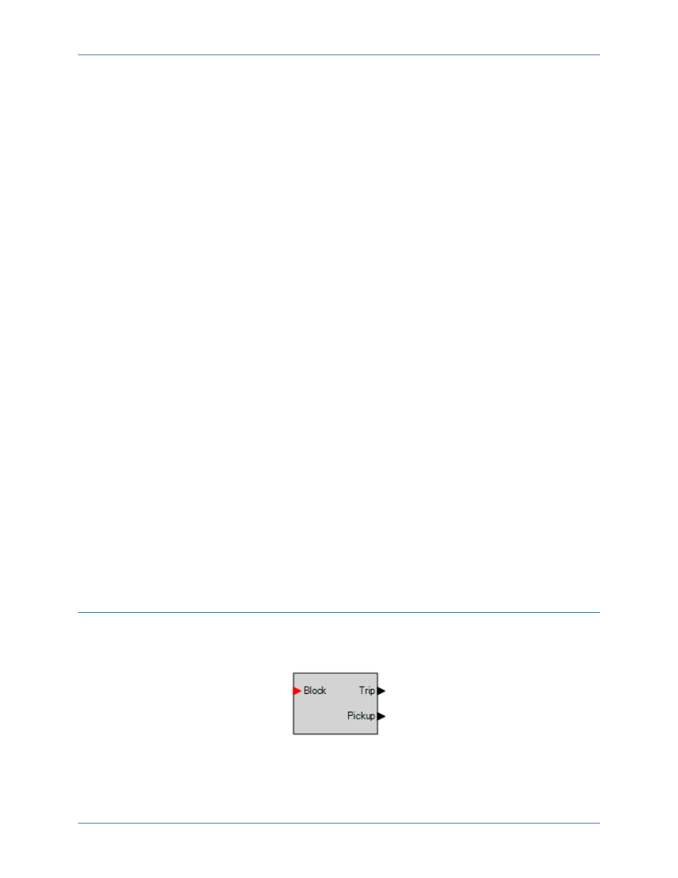
Logic Connections
Frequency element logic connections are made on the BESTlogicPlus screen in BESTCOMSPlus. The
frequency element logic block is illustrated in Figure 38. Logic inputs and outputs are summarized in
Table 14.
Figure 38. Frequency Element Logic Block
BE1-11m
Frequency (81) Protection