Tagging of breaker control switch, Logic connections – Basler Electric BE1-11m User Manual
Page 138
126
9424200996 Rev L
1.
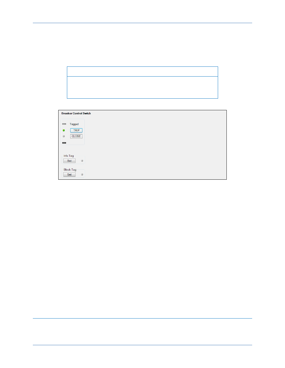
Use the Metering Explorer to open the Control/Breaker Control Switch tree branch (Figure 92).
2.
Click on either the TRIP or CLOSE button to select it. Login may be required. The green
selection indicator will begin to flash.
3.
Click on the TRIP or CLOSE button a second time to operate it. The green selection indicator will
stop flashing and the proper status indicator will light.
Note
If Step 3 is not performed within 25 seconds of Step 2, the button will
stop flashing and either the TRIP or CLOSE button will have to be re-
selected.
Figure 92. Breaker Control Switch Control Screen
Tagging of Breaker Control Switch
The breaker control switch provides tagging to indicate that the switch function is, or may be, under
revision. There are two tagging modes, Informational and Blocking. When in Informational mode, the
switch will still be operational when tagged. When in the Blocking mode, the switch will not be operational
while tagged. A tagged switch is indicated by an amber indicator on this screen.
Tagging of the breaker control switch can be accomplished through the front panel and through
BESTCOMSPlus. Use the Metering Explorer in BESTCOMSPlus to open the Control/Breaker Control
Switch tree branch. Click on the Set button for Informational Tag, Blocking Tag, or both. If tagging is
successful, a green LED to the right of the Set button will light.
The Blocking Tag has priority over the Informational Tag. Once the Blocking Tag has been placed, the
Informational Tag cannot be changed until the Blocking Tag is removed. In other words, you must choose
to place the Informational Tag before placing the Blocking Tag.
Each tag is placed with an “owner”. A tag must be removed by the same “owner” that placed it. For
example, if a tag is placed through BESTCOMSPlus, it can be removed only through BESTCOMSPlus. It
cannot be removed through the front panel. If a tag is placed through the front panel, it can be removed
only through the front panel. This applies for all other forms of communication when placing tags.
A 101 Tag alarm is also provided to indicate that the 101 is tagged. Refer to the
chapter for
information on how to program alarms.
Logic Connections
Breaker control element logic connections are made on the BESTlogicPlus screen in BESTCOMSPlus.
The breaker control element logic block is illustrated in Figure 93. All logic inputs use rising-edge
detection for recognition. Logic inputs and outputs are summarized in Table 52.
Breaker Control Switch (101)
BE1-11m